
Page 76 - Subyek Teknik Mesin - Forsthoffers Best Practice Handbook for Rotating Machinery by William E Forsthoffer
P. 76
Be st Practice 2 .8 Pump Best Practices
Best
Best
Best Practice 2.8Practice 2.8Practice 2.8
Monitor pump EROE in control room for critical centrifugal It has been my experience that majority of centrifugal pump me-
pumps and define EROE targets. chanical seal and bearing failures are the result of the pump being
Pump flow range can be monitored in the control room by inputting forced out of the EROE by changes in process required head (inlet
the pump shop test curve and dumping the following transmitter sig- pressure, discharge pressure and/or specific gravity) without the
nals into spreadsheets to calculate the pump head and flow: operators being aware of this.
Inlet pressure Benchmarks
Discharge pressure
This best practice has been followed since 2000 in heavy oil field pump
Flow
applications, where the operating conditions require the use of slurry
SG e A constant value input from actual liquid sample
pumps which are subject to rapid wear. The use of control room op-
EROE targets should be established in flow or the following other erating point monitoring with EROE alarms has extended pump MTBFs
methods if flow meters are not installed for each pump: to over 36 months, from less than 12 months before this best practice
was implemented.
Control valve position
Motor amps
Pump inlet and discharge piping differential temperature
Lessons Learned
Critical centrifugal and ‘bad actor pumps’ require constant
surveillance by operators to ensure optimum safety and
reliability.
B.P. 2.8. Supporting Material
Please refer to B.P: 2.7 for additional supporting material.
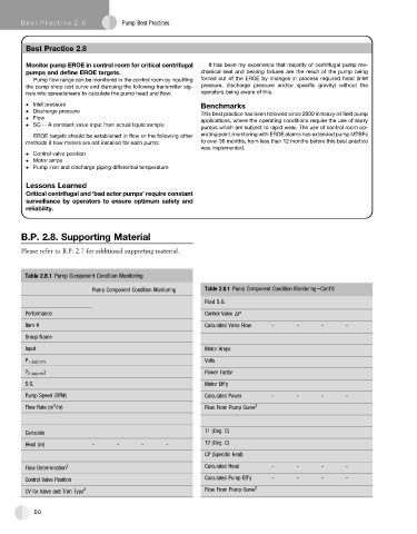
Table 2.8.1 Pump Component Condition Monitoring
Pump Component Condition Monitoring Table 2.8.1 Pump Component Condition MonitoringeCont'd
Fluid S.G.
Performance Control Valve DP
Item # Calculated Valve Flow - - - -
Group Name
Input Motor Amps
P 1 (kg/cm 2 ) Volts
P 2 (kg/cm 2) Power Factor
S.G. Motor Eff’y
Pump Speed (RPM) Calculated Power - - - -
3
Flow Rate (m /hr) Flow From Pump Curve 3
Calculate T1 (Deg. C)
Head (m) - - - - T2 (Deg. C)
CP (Specific Heat)
Flow Determination 1 Calculated Head - - - -
Control Valve Position Calculated Pump Eff’y - - - -
CV for Valve and Trim Type 2 Flow From Pump Curve 3
50