
Page 71 - Subyek Teknik Mesin - Forsthoffers Best Practice Handbook for Rotating Machinery by William E Forsthoffer
P. 71
Pump Best Practices Be st Practice 2.7
Best
Best Practice 2.7Practice 2.7
Operate centrifugal pumps within the “Equipment Re- We have found that approximately 80% of centrifugal
liability Operating Envelope” (EROE) to achieve maximum pump reliability reductions (sources of low MTBF) are due
mean time between failure (MTBF). to process changes that cause the pump to operate in
The Equipment Reliability Operating Envelope (EROE), also called either a high flow or low flow range. This exposes the pump
the ‘heart of the curve’, assures maximum centrifugal pump MTBF by to hydraulic disturbances resulting in low MTBF.
avoiding all operating areas of hydraulic disturbances. Establishing operator EROE targets for all critical site pumps and all
We define the general EROE range as þ 10% to 50% in flow from bad actor pumps (pumps with one or more component failures per
the pump best efficiency point. year) will ensure optimum centrifugal pump safety and MTBFs.
This range will be reduced for double flow pumps and high speed
inducer (see B.P: 2.6) pumps. Please refer to the supporting material Benchmarks
below for additional details.
This best practice has been used since the late 1990s in refineries,
chemical plants and in SAGD (steam assisted gravity drainage) appli-
Lessons Learned cations in heavy oil fields. Once this best practice had been imple-
Failure to establish EROE limits will lead to low MTBF of mented, pump MTBFs that were less than 12 months (“bad actors”)
centrifugal pumps were improved to greater than 80 months.
B.P. 2.7. Supporting Material Centrifugal (kinetic) pumps and their drivers
Centrifugal pumps increase the pressure of the liquid by
Effects of the process on pump reliability
using rotating blades to first increase its velocity, and then
and MTBF reduce the velocity of the liquid in the volute. Refer again to
Figure 2.7.2.
The effect of the process on machinery reliability is often A good analogy to this procedure is a football (soccer) game.
neglected as a root cause of machinery failure. It is a fact that When the ball (liquid molecule) is kicked, the leg (vane) in-
process condition changes can cause damage and/or failure to creases its velocity. When the goal tender (volute), (hopefully)
every major machinery component. For this discussion, the most catches the ball, its velocity is significantly reduced and the
common type of driven equipment e pumps will be used. pressure in the ball (molecule) is increased. If an instant replay
There are two (2) major classifications of pumps; positive ‘freeze shot’ picture is taken of the ball at this instant, it will
displacement and kinetic, of which centrifugal types are the show that its volume is reduced and its pressure is increased.
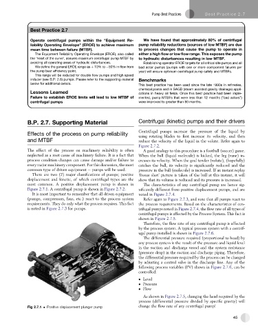
most common. A positive displacement pump is shown in The characteristics of any centrifugal pump are hence sig-
Figure 2.7.1. A centrifugal pump is shown in Figure 2.7.2. nificantly different from positive displacement pumps, and are
It is most important to remember that all driven equipment noted in Figure 2.7.4.
(pumps, compressors, fans, etc.) react to the process system Refer again to Figure 2.7.3, and note that all pumps react to
requirements. They do only what the process requires. This fact the process requirements. Based on the characteristics of cen-
is noted in Figure 2.7.3 for pumps. trifugal pumps noted in Figure 2.7.4, the flow rate of all types of
centrifugal pumps is affected by the Process System. This fact is
shown in Figure 2.7.5.
Therefore, the flow rate of any centrifugal pump is affected
by the process system. A typical process system with a centrif-
ugal pump installed is shown in Figure 2.7.6.
The differential pressure required (proportional to head) by
any process system is the result of the pressure and liquid level
in the suction and discharge vessel and the system resistance
(pressure drop) in the suction and discharge piping. Therefore,
the differential pressure required by the process can be changed
by adjusting a control valve in the discharge line. Any of the
following process variables (PV) shown in Figure 2.7.6, can be
controlled:
Level
Pressure
Flow
As shown in Figure 2.7.5, changing the head required by the
process (differential pressure divided by specific gravity) will
Fig 2.7.1 Positive displacement plunger pump change the flow rate of any centrifugal pump!
45