
Page 74 - Subyek Teknik Mesin - Forsthoffers Best Practice Handbook for Rotating Machinery by William E Forsthoffer
P. 74
Be st Practice 2 .7 Pump Best Practices
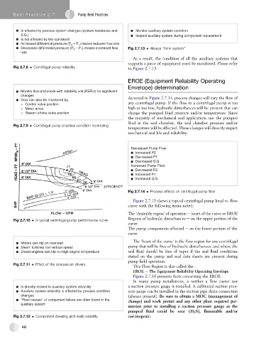
Is affected by process system changes (system resistance and Monitor auxiliary system condition
S.G.) Inspect auxiliary system during component replacement
Is not affected by the operators!
– P ) means reduced flow rate
Increased differential pressure (P 2 1
– P ) means increased flow
Decreased differential pressure (P 2 1 Fig 2.7.13 Always "think system"
rate
As a result, the condition of all the auxiliary systems that
supports a piece of equipment must be monitored. Please refer
Fig 2.7.8 Centrifugal pump reliability to Figure 2.7.13.
EROE (Equipment Reliability Operating
Envelope) determination
Monitor flow and check with reliability unit (RERU) for significant
changes
Flow can also be monitored by: As noted in Figure 2.7.14, process changes will vary the flow of
Control valve position any centrifugal pump. If the flow to a centrifugal pump is too
Motor amps high or too low, hydraulic disturbances will be present that can
Steam turbine valve position change the pumped fluid pressure and/or temperature. Since
the majority of mechanical seal applications use the pumped
fluid in the seal chamber, the seal chamber pressure and/or
Fig 2.7.9 Centrifugal pump practical condition monitoring
temperature will be affected. These changes will directly impact
mechanical seal life and reliability.
Decreased Pump Flow:
Increased P2
Decreased P1
Decreased S.G.
Increased Pump Flow:
Decreased P2
Increased P1
Increased S.G.
Fig 2.7.14 Process effects on centrifugal pump flow
Figure 2.7.15 shows a typical centrifugal pump head vs. flow
curve with the following items noted:
The ‘desirable region’ of operation e heart of the curve or EROE
Regions of hydraulic disturbances e on the upper portion of the
Fig 2.7.10 A typical centrifugal pump performance curve
curve
The pump components affected e on the lower portion of the
curve
The ‘heart of the curve’ is the flow region for any centrifugal
Motors can trip on overload
Steam turbines can reduce speed pump that will be free of hydraulic disturbances, and where the
Diesel engines can trip on high engine temperature seal fluid should be free of vapor if the seal fluid conditions
stated on the pump and seal data sheets are present during
pump field operation.
Fig 2.7.11 Effect of the process on drivers
This Flow Region is also called the:
EROE e The Equipment Reliability Operating Envelope
Figure 2.7.16 presents facts concerning the EROE.
In many pump installations, a neither a flow meter nor
Is directly related to auxiliary system reliability a suction pressure gauge is installed. A calibrated suction pres-
Auxiliary system reliability is affected by process condition sure gauge can be installed in the suction pipe drain connection
changes
(always present). Be sure to obtain a MOC (management of
“Root causes” of component failure are often found in the
auxiliary system change) and work permit and any other plant required per-
mission prior to installing a suction pressure gauge as the
pumped fluid could be sour (H 2 S), flammable and/or
Fig 2.7.12 Component (bearing and seal) reliability carcinogenic.
48