
Page 77 - Subyek Teknik Mesin - Forsthoffers Best Practice Handbook for Rotating Machinery by William E Forsthoffer
P. 77
Pump Best Practices Be st Practice 2.9
Table 2.8.1 Pump Component Condition MonitoringeCont'd Table 2.8.1 Pump Component Condition MonitoringeCont'd
Pump Maintenance Required 4 Notes
1. If a flow meter is not available, the pump flow will be determined by one of
the alternative methods noted in tab 7 of the supplementary manual. These
EROE Determination
alternative methods are: 1. Portable Ultrasonic Flowmeter 2. Control Valve
BEP Flow 5 Position to calculate flow 3. Motor Amps to calculate power 4. Pump D Tto
calculate pump efficiency.
EROE Min Flow - - - -
2. The CV can be found on the valve manufacturer's curve for specific valve
EROE Max Flow - - - - type and trim. Note that most of the major valve manufacturers post these
Is Pump in EROE - - - - curves on their websites.
3. Flow will be estimated using the original shop test curve. Note that if the
pump is not in good condition these estimates will not be very accurate.
EROE Targets for Operations
4. Pump maintenance should be considered if the head and flow (operating
Flow point) when plotted on the test curve is approx. 10% below test curve flow
for calculated head.
Amps
5. Flow at highest efficiency taken from the shop test curve in the
Pump D T (Measured on Inlet
and Discharge Pipes) supplementary manual.
Best Practice 2.9Practice 2.9Practice 2.9
Best
Best
Ensure that centrifugal pumps have a minimum head rise flow will reduce to zero with any increase in head required
to shutoff (zero flow) of 7%. by the process, and subject the pump to extensive damage
The lower the head rise of a centrifugal pump (pump head produced and possible seizing.
at zero flow divided by head produced at rated point), the greater the Centrifugal pumps with flat head curves have been subject to ex-
change in pump flow for a given change in process head required. tensive damage resulting from minimum flow bypass valves not
The operating flow for centrifugal pumps with head rises that are opening when required. Pumps with head rise less than 5% are usually
below 7% will be easily changed by small variances in the process ‘bad actors’ (more than one failure per year).
head required.
Try to select a centrifugal pump with the highest head rise possible, Benchmarks
while taking into consideration the flow range and NPSH available for This best practice has been used since the mid-1970s to ensure
the required pump. highest centrifugal pump safety and MTBF (greater than 80 months) in
all pump applications.
Lessons Learned
Centrifugal pump flow is determined by the head required
by the process. If the pump curve is flat (zero head rise),
B.P. 2.9. Supporting Material
The centrifugal curve
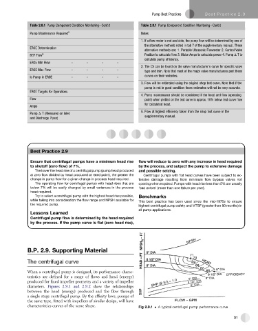
When a centrifugal pump is designed, its performance charac-
teristics are defined for a range of flows and head (energy)
produced for fixed impeller geometry and a variety of impeller
diameters. Figures 2.9.1 and 2.9.2 show the relationships
between the head (energy) produced and the flow through
a single stage centrifugal pump. By the affinity laws, pumps of
the same type, fitted with impellers of similar design, will have
characteristics curves of the same shape. Fig 2.9.1 A typical centrifugal pump performance curve
51