
Page 78 - Subyek Teknik Mesin - Forsthoffers Best Practice Handbook for Rotating Machinery by William E Forsthoffer
P. 78
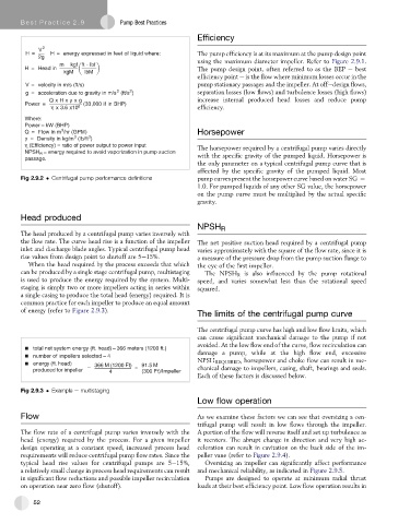
Be st Practice 2 .9           Pump Best Practices
                                                            Efficiency

             V  2
         H=     H = energy expressed in feet of liquid where:  The pump efficiency is at its maximum at the pump design point
            2g
                   m  kgf ft - lbf                          using the maximum diameter impeller. Refer to Figure 2.9.1.
        H = Head in                                         The pump design point, often referred to as the BEP e best
                    kgM   lbM
                                                            efficiency point e is the flow where minimum losses occur in the
         V = velocity in m/s (ft/s)                         pump stationary passages and the impeller. At offedesign flows,
                                        2
                                    2
         g = acceleration due to gravity in m/s (ft/s )     separation losses (low flows) and turbulence losses (high flows)
                QxHx ρ xg                                   increase internal produced head losses and reduce pump
        Power =           (33,000 if in BHP)
                η x 3.6 x10 6                               efficiency.
        Where:
        Power – kW (BHP)
                   3
        Q = Flow in m /hr (GPM)                             Horsepower
                       3
                           3
        ρ = Density in kg/m (lb/ft )
        η (Efficiency) = ratio of power output to power input
                                                            The horsepower required by a centrifugal pump varies directly
              = energy required to avoid vaporization in pump suction
        NPSH R
                                                            with the specific gravity of the pumped liquid. Horsepower is
        passage.
                                                            the only parameter on a typical centrifugal pump curve that is
                                                            affected by the specific gravity of the pumped liquid. Most
       Fig 2.9.2   Centrifugal pump performance definitions  pump curves present the horsepower curve based on water SG ¼
                                                            1.0. For pumped liquids of any other SG value, the horsepower
                                                            on the pump curve must be multiplied by the actual specific
                                                            gravity.
       Head produced
                                                            NPSH   R
       The head produced by a centrifugal pump varies inversely with
       the flow rate. The curve head rise is a function of the impeller  The net positive suction head required by a centrifugal pump
       inlet and discharge blade angles. Typical centrifugal pump head  varies approximately with the square of the flow rate, since it is
       rise values from design point to shutoff are 5e15%.  a measure of the pressure drop from the pump suction flange to
          When the head required by the process exceeds that which  the eye of the first impeller.
       can be produced by a single stage centrifugal pump, multistaging  The NPSH R is also influenced by the pump rotational
       is used to produce the energy required by the system. Multi-  speed, and varies somewhat less than the rotational speed
       staging is simply two or more impellers acting in series within  squared.
       a single casing to produce the total head (energy) required. It is
       common practice for each impeller to produce an equal amount
       of energy (refer to Figure 2.9.3).
                                                            The limits of the centrifugal pump curve

                                                            The centrifugal pump curve has high and low flow limits, which
                                                            can cause significant mechanical damage to the pump if not
                                                            avoided. At the low flow end of the curve, flow recirculation can
           total net system energy (ft. head) – 366 meters (1200 ft.)
           number of impellers selected – 4                 damage a pump, while at the high flow end, excessive
                                                            NPSH REQUIRED , horsepower and choke flow can result in me-
           energy (ft. head)  366 M (1200 Ft)  91.5 M
                           –             =                  chanical damage to impellers, casing, shaft, bearings and seals.
           produced for impeller  4        (300 Ft)/Impeller
                                                            Each of these factors is discussed below.
       Fig 2.9.3   Example e multistaging
                                                            Low flow operation

       Flow                                                 As we examine these factors we can see that oversizing a cen-
                                                            trifugal pump will result in low flows through the impeller.
       The flow rate of a centrifugal pump varies inversely with the  A portion of the flow will reverse itself and set up turbulence as
       head (energy) required by the process. For a given impeller  it reenters. The abrupt change in direction and very high ac-
       design operating at a constant speed, increased process head  celeration can result in cavitation on the back side of the im-
       requirements will reduce centrifugal pump flow rates. Since the  peller vane (refer to Figure 2.9.4).
       typical head rise values for centrifugal pumps are 5e15%,  Oversizing an impeller can significantly affect performance
       a relatively small change in process head requirements can result  and mechanical reliability, as indicated in Figure 2.9.5.
       in significant flow reductions and possible impeller recirculation  Pumps are designed to operate at minimum radial thrust
       on operation near zero flow (shutoff).                loads at their best efficiency point. Low flow operation results in

           52