
Page 67 - Subyek Teknik Mesin - Forsthoffers Best Practice Handbook for Rotating Machinery by William E Forsthoffer
P. 67
Pump Best Practices Be st Practice 2.6
during the operation of equipment. Installation of piping to
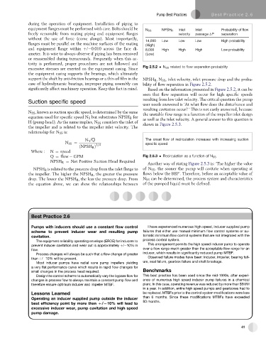
equipment flanges must be performed with care. Bolts should be Inlet Inlet Probability of flow
N SS NPSH R
freely removable from mating piping and equipment flanges velocity passage ΔP separation
without the use of force (come alongs). Most importantly, 14,000 Low Low Low High probability
flanges must be parallel on the machine surfaces of the mating (High)
and equipment flange within þ/ 0.010 across the face di- 8,000 High High High Low probability
ameter. It is wise to always observe if piping has been removed (Low)
or reassembled during turnarounds. Frequently when this ac-
tivity is performed, proper procedures are not followed and
excessive stresses are exerted on the equipment casing. Since Fig 2.5.2 N SS related to flow separation probability
the equipment casing supports the bearings, which ultimately
support the shaft by anti-friction bearings or a thin oil film in the NPSH R ,N SS , inlet velocity, inlet pressure drop and the proba-
case of hydrodynamic bearings, improper piping assembly can bility of flow separation in Figure 2.5.2.
significantly affect machinery operation. Keep this fact in mind. Based on the information presented in Figure 2.5.2, it can be
seen that flow separation will occur for high specific speeds
resulting from low inlet velocity. The critical question the pump
Suction specific speed
user needs answered is ‘At what flow does the disturbance and
resulting cavitation occur? ’ This is not easily answered, because
N SS , known as suction specific speed, is determined by the same the unstable flow range is a function of the impeller inlet design
equation used for specific speed N S but substitutes NPSH R for as well as the inlet velocity. A general answer to this question is
H (pump head). As the name implies, N SS considers the inlet of shown in Figure 2.5.3.
the impeller and is related to the impeller inlet velocity. The
relationship for N SS is:
p
N Q The onset flow of recirculation increases with increasing suction
ffiffiffiffiffi
N SS ¼ specific speed
3=4
ðNPSH R Þ
Where : N ¼ speed
Q ¼ flow GPM Fig 2.5.3 Recirculation as a function of N SS
NPSH R ¼ Net Positive Suction Head Required
Another way of stating Figure 2.5.3 is: ‘The higher the value
NPSH R is related to the pressure drop from the inlet flange to of N SS , the sooner the pump will cavitate when operating at
the impeller. The higher the NPSH R , the greater the pressure flows below the BEP’. Therefore, before an acceptable value of
drop. The lower the NPSH R , the less the pressure drop. From N SS can be determined, the process system and characteristics
the equation above, we can show the relationships between of the pumped liquid must be defined.
Best Practice 2.6Practice 2.6
Best
Pumps with inducers should use a constant flow control I have experienced numerous high speed, inducer supplied pump
scheme to prevent inducer wear and resulting pump failures that either use manual minimum flow control systems or au-
cavitation. tomatic minimum flow control systems that are not integrated with the
The equipment reliability operating envelope (EROE) for inducers to process control system.
prevent inducer cavitation and wear out is approximately þ/ 10% in This arrangement permits the high speed inducer pump to operate
flow. over a flow range much greater than the acceptable flow range for an
Process changes will always be such that a flow change of greater inducer, which results in significantly reduced pump MTBF.
than þ/ 10% will be present. Observed failure modes have been: inducer, impeller, bearing fail-
Most inducer pumps have radial vane pump impellers yielding ure, seal failure, gearbox failure and shaft breakage.
a very flat performance curve which results in rapid flow changes for
small changes in the process head required. Benchmarks
Design the control scheme to automatically vary the bypass flow for This best practice has been used since the mid-1990s, after experi-
changes in process flow to always maintain a constant pump flow and ence of numerous high speed inducer pump failures in a chemical
therefore ensure optimum inducer and impeller MTBF. plant. In this case, operating revenue was reduced by more than $5MM
in a year. In addition, entire high speed pumps and gearboxes had to
Lessons Learned be replaced. MTBFs prior to the control system modifications were less
than 6 months. Since these modifications MTBFs have exceeded
Operating an inducer supplied pump outside the inducer
80 months.
best efficiency point by more than D/L10% will lead to
excessive inducer wear, pump cavitation and high speed
pump damage.
41