
Page 65 - Subyek Teknik Mesin - Forsthoffers Best Practice Handbook for Rotating Machinery by William E Forsthoffer
P. 65
Pump Best Practices Be st Practice 2.4
This figure illustrates a horizontal split casing design, which
allows the rotor to be removed vertically after the top half casing
is unbolted. This type of pump is normally limited to working
pressure of approximately 13,790 kpa (2000 psi), temperatures
of up to 315 C (600 F) and S.G. of 0.7 or greater. Impeller
configuration for this type of pump can be either ‘inline’ or
‘opposed’. The ‘opposed’ impeller arrangement has the advan-
tage of not requiring a thrust balancing device, which is required
for the ‘inline’ configuration.
Multistage barrel Fig 2.4.8 Single volute casing form
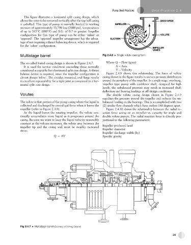
The so-called barrel casing design is shown in Figure 2.4.7. Where Q ¼ Flow (gpm)
It is used for service conditions exceeding those normally A ¼ Area
considered acceptable for a horizontal split case design. A thrust V ¼ Velocity
balance device is required, since the impeller configuration is Figure 2.4.8 shows this relationship. The form of volute
almost always ‘inline’. The circular, mounted, end flange results casing shown in the figure results in uneven pressure distribution
in excellent repeatability for a tight joint as compared to a hor- around the periphery of the impeller. In a single stage, overhung,
izontal split case design. impeller type pump with cantilever shaft, designed for high
heads, the unbalanced pressure may result in increased shaft
deflection and bearing loadings at off-design conditions.
Volutes The double volute casing design shown in Figure 2.4.9
equalizes the pressure around the impeller and reduces the un-
The volute is that portion of the pump casing where the liquid is balanced loading on the bearings. This is accomplished with two
collected and discharged by centrifugal force when it leaves the (2) similar flow channels which have outlets 180 degrees apart.
impeller (refer to Figure 2.4.8). Figure 2.4.10 shows the relationship between the radial re-
As the liquid leaves the rotating impeller, the volute con- action force acting on an impeller vs. capacity for single and
tinually accumulates more liquid as it progresses around the double volute pumps. The radial reaction force is directly pro-
casing. Because we want to keep the liquid velocity reasonably portional to the following parameters:
constant as the volume increases, the volute area between the
impeller tip and the casing wall must be steadily increased Impeller produced head
since: Impeller diameter
Impeller discharge width (b 2 )
Q ¼ AV Specific gravity
Fig 2.4.7 Multistage barrel (Courtesy of Demag Delaval)
39