
Page 61 - Subyek Teknik Mesin - Forsthoffers Best Practice Handbook for Rotating Machinery by William E Forsthoffer
P. 61
Pump Best Practices Be st Practice 2.3
flange of the pump, which is required to maintain the fluid in When calculating NPSH available it is prudent to incorporate
a liquid state. In a centrifugal pump it is usually measured in feet a margin of safety to protect the pump from potential cavitation
of liquid (refer to Figure 2.3.3 for a typical method for calcu- damage resulting from unexpected upsets. The actual margin
lating NPSH available). It is important to note that the pressure will vary from company to company. Some will use the normal
at the suction source cannot be considered equal to the NPSH. liquid level as the datum point, while others use the vessel
In Figure 2.3.3 it can be seen that the source pressure is the tangent or the bottom of the vessel. Typical suggested margins
same as the vapor pressure, indicating that the liquid is at its are: two (2) feet for hydrocarbon liquids (including low S.G.),
boiling point. and ten (10) feet for boiling water.
When the vapor pressure is subtracted from the suction
pressure, the resulting NPSH available is 2.1 psi or ten (10) feet.
Defining the pump rated point for efficient
operation
Since centrifugal pumps are not normally custom designed
When selecting a specific impeller pattern the ratedflow should items of equipment, it is important to ensure that each vendor
be no greater than ten (10) percent to the right of best efficiency
will quote similar pump configurations for the specific operating
point. This will result in operation at close to best efficiency point conditions set forth on each application data sheet. When
during normal operation. Also, selecting a pump to operate too
establishing which pump characteristic and impeller pattern to
far to the right of best efficiency point can result in the pump
operating in the ‘break’. A pump is considered operating in the select for a specific application, certain guidelines should be
‘break’ when it is pumping maximum capacity and the total head followed (refer to Figure 2.3.4).
is reduced while the suction head is held (the impeller actually An accurate definition of all liquid and hydraulic condi-
acts as an orifice to limit the flow). tions along with a proper centrifugal pump selection will
Selecting a pump for the rated flow too far to the left of best ensure operation within the “Heart of the Curve”,also
efficiency point (oversized pump) can result in cavitation known as the Equipment Reliability Operating Envelope
damage caused by internal recirculation.
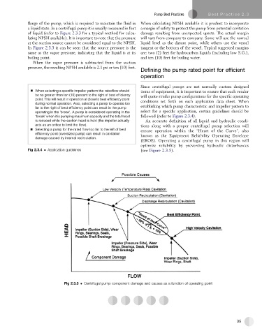
(EROE). Operating a centrifugal pump in this region will
optimize reliabilitybypreventing hydraulic disturbances
Fig 2.3.4 Application guidelines (see Figure 2.3.5).
Fig 2.3.5 Centrifugal pump component damage and causes as a function of operating point
35