
Page 57 - Subyek Teknik Mesin - Forsthoffers Best Practice Handbook for Rotating Machinery by William E Forsthoffer
P. 57
Pump Best Practices Be st Practice 2.2
Select pump type based on guidelines: q i L d i u B r e l i o e f e d w r e t a
Single stage overhung impeller . S G . 9 . 0 3
Multi stage axial or radial split casing design . T . P 2 2 0 F
Match NPSHR vs. NPSHA P s 25 psig
Calculate bhp based on pump efficiency P d 650 psig
Determine driver hp rating based on API criteria NPSA available 26 ft
o l F w e t a r e t a r d 2 7 5 g p m
head required 1553 ft.
Fig 2.2.19 Tasks for selecting pump and driver
system exceeds the head (energy) which can be provided by a 15 Fig 2.2.21 Example No. 2: operating conditions
inch single stage impeller.
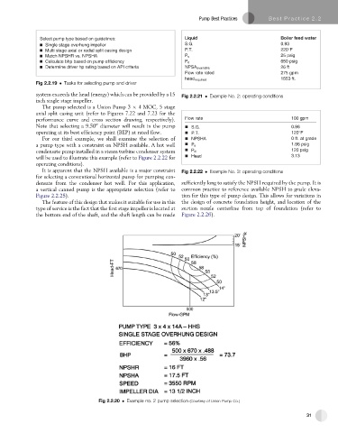
The pump selected is a Union Pump 3 4 MOC, 5 stage
axial split casing unit (refer to Figures 7.22 and 7.23 for the
performance curve and cross section drawing, respectively). o l F w e t a r 1 0 0 g p m
Note that selecting a 9.50 diameter will result in the pump . S G . 9 . 0 8
00
operating at its best efficiency point (BEP) at rated flow. . T . P 1 2 0 F
For our third example, we shall examine the selection of N P S H A 0 . t f t a a r g d e
a pump type with a constraint on NPSH available. A hot well P s 1.96 psig
condensate pump installed in a steam turbine condenser system P d 120 psig
will be used to illustrate this example (refer to Figure 2.2.22 for H e a d 1 . 3 3
operating conditions).
It is apparent that the NPSH available is a major constraint Fig 2.2.22 Example No. 3: operating conditions
for selecting a conventional horizontal pump for pumping con-
densate from the condenser hot well. For this application, sufficiently long to satisfy the NPSH required by the pump. It is
a vertical canned pump is the appropriate selection (refer to common practice to reference available NPSH to grade eleva-
Figure 2.2.25). tion for this type of pump design. This allows for variations in
The feature of this design that makes it suitable for use in this the design of concrete foundation height, and location of the
type of service is the fact that the first stage impeller is located at suction nozzle centerline from top of foundation (refer to
the bottom end of the shaft, and the shaft length can be made Figure 2.2.26).
Fig 2.2.20 Example no. 2 pump selection (Courtesy of Union Pump Co.)
31