
Page 56 - Subyek Teknik Mesin - Forsthoffers Best Practice Handbook for Rotating Machinery by William E Forsthoffer
P. 56
Be st Practice 2 .2 Pump Best Practices
Used for high head low flow applications
Total maximum head approximately 762 meters (2500 ft)
Can be used for all temperatures
(can use inducer)
Lowest NPSH required
Limited to 300 kW (400 bhp) maximum
All process services with proper material selection
Incorporates gear box to increase pump speeds as high as
30,000 rpm
Fig 2.2.14 Single stage integral gear centrifugal pump
characteristics
3
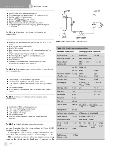
Used for high flow applications (greater than 455 M /hr [2000 Fig 2.2.18 Example No. 1: process system
gpm])
Low, medium head requirements
Low NPSH required Table 2.2.1 Calculate process system variables
Low, medium high temperature (with cooled bearings, stuffing
box) Elevations above grade: Discharge pressure calculation:
All process services with proper materials selection
Center of gravity of impeller is between bearing span Pump centerline 3ft Vessel pressure 310 psig
No speed constraint Inlet nozzle to vessel 72ft Static elevation head
Low axial thrust
Confirm that suction specific speed is less than 9,000. Liquid surface in (72-3) 0.433 ¼ 14.5 psi
(Definition and equation is in Chapter 8) suction vessel 0.488
max 32ft Friction 6P:
Fig 2.2.15 Single stage, double suction impeller between bearing
pump characteristics min 22 ft Piping 10 psi
Pressure p, in bottom 237 psig Orifice 2 psi
of suction vessel Control valve 30 psi
Pressure drops: Exchanger 15 psi
Used for high head medium flow applications
Double suction impeller for first stage for low NPSH R Suction piping 1 psi Pd (Vessel press þ ¼ 381.5 psi
Low, medium, high temperature (with cooled bearings, stuffing Elev press þ losses)
box)
No speed constraint Discharge piping 10 psi 6P PdePs
Thrust requires compensation (back to back impellers, balance
device) Flow orifice 2 psi 381.5e240
Control valve 30 psi 141.5 psi
Fig 2.2.16 Horizontal multistage between bearing pump Exchanger 15 psi
characteristics
Flow rate: 500 gpm
Specific gravity 0.488 @ 6P 2:31 141:5 2:31 ¼ 670 ft
p.t. s:g: ¼ 0:488
Used for low NPSH available applications
High head capability by adding stages Vapor pressure 251 psia
Low, medium, high temperature
Low, medium flow range Suction pressure calculation: NPSH AVAILABLE (for boiling liquid)
No speed constraint
Most non abrasive process liquids with proper materials Vessel pressure 237 psig p a surface þ 14.7 e P v þ
selection
Static elevation head static elev diff e friction
(22-3) 0.433 ¼ 4 psi 237 þ 14.7 e 251 þ 4 e 1 ¼ 3.7 psi
Fig 2.2.17 Vertical multistage pump characteristics
0.488 3:7 2:31
NPSH AVAILABLE ¼ 0:486 ¼ 17:5ft
we can determine that the pump defined in Figure 2.2.19 Suction line 6p e1 psi
satisfies all of the guidelines.
For example no. 2 let us select a pump for a boiler feed water
application with operating conditions shown in Figure 2.2.20. P s (Vessel press þ ¼ 240 psi
This application requires a multi-stage, axial, split case pump Elev press loss)
based on the criteria that the head (energy) required by the
30