
Page 126 - T. Anderson-Fracture Mechanics - Fundamentals and Applns.-CRC (2005)
P. 126
1656_C003.fm Page 106 Monday, May 23, 2005 5:42 PM
106 Fracture Mechanics: Fundamentals and Applications
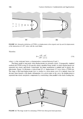
FIGURE 3.4 Alternative definitions of CTOD: (a) displacement at the original crack tip and (b) displacement
at the intersection of a 90° vertex with the crack flanks.
Therefore
rW − a V
(
)
δ = (3.9)
( − rW + a) a
where r is the rotational factor, a dimensionless constant between 0 and 1.
The hinge model is inaccurate when displacements are primarily elastic. Consequently, standard
methods for CTOD testing [5, 6] typically adopt a modified hinge model, in which displacements are
separated into elastic and plastic components; the hinge assumption is applied only to plastic dis-
placements. Figure 3.6 illustrates a typical load (P) vs. displacement (V) curve from a CTOD test.
The shape of the load-displacement curve is similar to a stress-strain curve: It is initially linear but
deviates from linearity with plastic deformation. At a given point on the curve, the displacement is
separated into elastic and plastic components by constructing a line parallel to the elastic loading line.
FIGURE 3.5 The hinge model for estimating CTOD from three-point bend specimens.