
Page 127 - T. Anderson-Fracture Mechanics - Fundamentals and Applns.-CRC (2005)
P. 127
1656_C003.fm Page 107 Monday, May 23, 2005 5:42 PM
Elastic-Plastic Fracture Mechanics 107
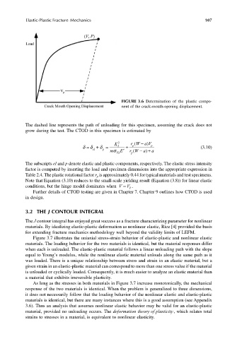
FIGURE 3.6 Determination of the plastic compo-
nent of the crack-mouth-opening displacement.
The dashed line represents the path of unloading for this specimen, assuming the crack does not
grow during the test. The CTOD in this specimen is estimated by
p K
2 rW − a V)
(
δ δ = el δ + p = m σ E YS I ′ + p ( − rW + a) p a (3.10)
The subscripts el and p denote elastic and plastic components, respectively. The elastic stress intensity
factor is computed by inserting the load and specimen dimensions into the appropriate expression in
Table 2.4. The plastic rotational factor r is approximately 0.44 for typical materials and test specimens.
p
Note that Equation (3.10) reduces to the small-scale yielding result (Equation (3.8)) for linear elastic
conditions, but the hinge model dominates when V V ≈ p ..
Further details of CTOD testing are given in Chapter 7. Chapter 9 outlines how CTOD is used
in design.
3.2 THE J CONTOUR INTEGRAL
The J contour integral has enjoyed great success as a fracture characterizing parameter for nonlinear
materials. By idealizing elastic-plastic deformation as nonlinear elastic, Rice [4] provided the basis
for extending fracture mechanics methodology well beyond the validity limits of LEFM.
Figure 3.7 illustrates the uniaxial stress-strain behavior of elastic-plastic and nonlinear elastic
materials. The loading behavior for the two materials is identical, but the material responses differ
when each is unloaded. The elastic-plastic material follows a linear unloading path with the slope
equal to Young’s modulus, while the nonlinear elastic material unloads along the same path as it
was loaded. There is a unique relationship between stress and strain in an elastic material, but a
given strain in an elastic-plastic material can correspond to more than one stress value if the material
is unloaded or cyclically loaded. Consequently, it is much easier to analyze an elastic material than
a material that exhibits irreversible plasticity.
As long as the stresses in both materials in Figure 3.7 increase monotonically, the mechanical
response of the two materials is identical. When the problem is generalized to three dimensions,
it does not necessarily follow that the loading behavior of the nonlinear elastic and elastic-plastic
materials is identical, but there are many instances where this is a good assumption (see Appendix
3.6). Thus an analysis that assumes nonlinear elastic behavior may be valid for an elastic-plastic
material, provided no unloading occurs. The deformation theory of plasticity, which relates total
strains to stresses in a material, is equivalent to nonlinear elasticity.