
Page 132 - T. Anderson-Fracture Mechanics - Fundamentals and Applns.-CRC (2005)
P. 132
1656_C003.fm Page 112 Monday, May 23, 2005 5:42 PM
112 Fracture Mechanics: Fundamentals and Applications
The actual stress and strain distributions are obtained by applying the appropriate boundary
conditions (see Appendix 3.4):
1
EJ n +1
σ σ = o σ ˜ θ n (, ) (3.24a)
ij
ασ Ir ij
2
on
and
n
ασ EJ n +1
ε = E ασ Ir ε ˜ ij θ n (, ) (3.24b)
o
ij
2
on
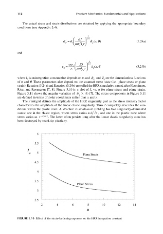
where I is an integration constant that depends on n, and ˜ σ ij and ˜ ε ij are the dimensionless functions
n
of n and q. These parameters also depend on the assumed stress state (i.e., plane stress or plane
strain). Equation (3.24a) and Equation (3.24b) are called the HRR singularity, named after Hutchinson,
Rice, and Rosengren [7, 8]. Figure 3.10 is a plot of I vs. n for plane stress and plane strain.
n
Figure 3.11 shows the angular variation of ˜ σ ij (n, q) [7]. The stress components in Figure 3.11
are defined in terms of polar coordinates rather than x and y.
The J integral defines the amplitude of the HRR singularity, just as the stress intensity factor
characterizes the amplitude of the linear elastic singularity. Thus J completely describes the con-
ditions within the plastic zone. A structure in small-scale yielding has two singularity-dominated
zones: one in the elastic region, where stress varies as 1 r , and one in the plastic zone where
stress varies as r − n+1/( 1) . The latter often persists long after the linear elastic singularity zone has
been destroyed by crack-tip plasticity.
FIGURE 3.10 Effect of the strain-hardening exponent on the HRR integration constant.