
Page 133 - T. Anderson-Fracture Mechanics - Fundamentals and Applns.-CRC (2005)
P. 133
1656_C003.fm Page 113 Monday, May 23, 2005 5:42 PM
Elastic-Plastic Fracture Mechanics 113
(a)
(b)
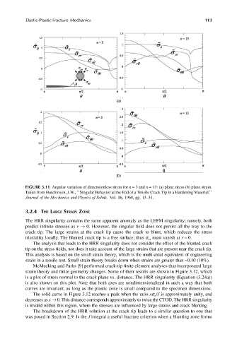
FIGURE 3.11 Angular variation of dimensionless stress for n = 3 and n = 13: (a) plane stress (b) plane strain.
Taken from Hutchinson, J.W., ‘‘Singular Behavior at the End of a Tensile Crack Tip in a Hardening Material.’’
Journal of the Mechanics and Physics of Solids, Vol. 16, 1968, pp. 13–31.
3.2.4 THE LARGE STRAIN ZONE
The HRR singularity contains the same apparent anomaly as the LEFM singularity; namely, both
predict infinite stresses as r → 0. However, the singular field does not persist all the way to the
crack tip. The large strains at the crack tip cause the crack to blunt, which reduces the stress
triaxiality locally. The blunted crack tip is a free surface; thus s must vanish at r = 0.
xx
The analysis that leads to the HRR singularity does not consider the effect of the blunted crack
tip on the stress fields, nor does it take account of the large strains that are present near the crack tip.
This analysis is based on the small strain theory, which is the multi-axial equivalent of engineering
strain in a tensile test. Small strain theory breaks down when strains are greater than ~0.10 (10%).
McMeeking and Parks [9] performed crack-tip finite element analyses that incorporated large
strain theory and finite geometry changes. Some of their results are shown in Figure 3.12, which
is a plot of stress normal to the crack plane vs. distance. The HRR singularity (Equation (3.24a))
is also shown on this plot. Note that both axes are nondimensionalized in such a way that both
curves are invariant, as long as the plastic zone is small compared to the specimen dimensions.
The solid curve in Figure 3.12 reaches a peak when the ratio xs /J is approximately unity, and
o
decreases as x → 0. This distance corresponds approximately to twice the CTOD. The HRR singularity
is invalid within this region, where the stresses are influenced by large strains and crack blunting.
The breakdown of the HRR solution at the crack tip leads to a similar question to one that
was posed in Section 2.9: Is the J integral a useful fracture criterion when a blunting zone forms