
Page 134 - T. Anderson-Fracture Mechanics - Fundamentals and Applns.-CRC (2005)
P. 134
1656_C003.fm Page 114 Monday, May 23, 2005 5:42 PM
114 Fracture Mechanics: Fundamentals and Applications
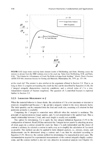
FIGURE 3.12 Large-strain crack-tip finite element results of McMeeking and Parks. Blunting causes the
stresses to deviate from the HRR solution close to the crack tip. Taken from McMeeking, R.M. and Parks,
D.M., ‘‘On Criteria for J-Dominance of Crack Tip Fields in Large-Scale Yielding.’’ Elastic Plastic Fracture
ASTM STP 668, American Society for Testing and Materials, Philadelphia, PA, 1979, pp. 175–194.
at the crack tip? The answer is also similar to the argument offered in Section 2.9. That is, as
long as there is a region surrounding the crack tip that can be described by Equation (3.24), the
J integral uniquely characterizes crack-tip conditions, and a critical value of J is a size-
independent measure of fracture toughness. The question of J controlled fracture is explored
further in Section 3.5.
3.2.5 LABORATORY MEASUREMENT OF J
When the material behavior is linear elastic, the calculation of J in a test specimen or structure is
relatively straightforward because J = G, and G is uniquely related to the stress intensity factor.
The latter quantity can be computed from the load and crack size, assuming a K solution for that
particular geometry is available.
Computing the J integral is somewhat more difficult when the material is nonlinear. The
principle of superposition no longer applies, and J is not proportional to the applied load. Thus a
simple relationship between J, load, and crack length is usually not available.
One option for determining J is to apply the line integral definition Equation (3.19) to the
configuration of interest. Read [10] has measured the J integral in test panels by attaching an array
of strain gages in a contour around the crack tip. Since J is path independent and the choice of
contour is arbitrary, he selected a contour in such a way as to simplify the calculation of J as much
as possible. This method can also be applied to finite element analysis, i.e., stresses, strains, and
displacements can be determined along a contour and J can then be calculated according to
Equation (3.19). However, the contour method for determining J is impractical in most cases. The
instrumentation required for experimental measurements of the contour integral is highly cumber-
some, and the contour method is also not very attractive in numerical analysis (see Chapter 12).