
Page 79 - T. Anderson-Fracture Mechanics - Fundamentals and Applns.-CRC (2005)
P. 79
1656_C02.fm Page 59 Thursday, April 14, 2005 6:28 PM
Linear Elastic Fracture Mechanics 59
energy that accompanies an increment of crack extension; the latter quantity characterizes the
stresses, strains, and displacements near the crack tip. The energy release rate describes global
behavior, while K is a local parameter. For linear elastic materials, K and G are uniquely related.
For a through crack in an infinite plate subject to a uniform tensile stress (Figure 2.3), G and
K are given by Equation (2.24) and Equation (2.41), respectively. Combining these two equations
I
leads to the following relationship between G and K for plane stress:
I
K 2
G = I (2.54)
E
2
For plane strain conditions, E must be replaced by E/(1 − ν ). To avoid writing separate expressions
for plane stress and plane strain, the following notation will be adopted throughout this book:
E ′= E for plane stress (2.55a)
and
E
E ′ = for plane strain (2.55b)
1 − v 2
Thus the G-K relationship for both plane stress and plane strain becomes
I
K 2
G = I (2.56)
′ E
Since Equation (2.24) and Equation (2.41) apply only to a through crack in an infinite plate, we
have yet to prove that Equation (2.56) is a general relationship that applies to all configurations. Irwin [9]
performed a crack closure analysis that provides such a proof. Irwin’s analysis is presented below.
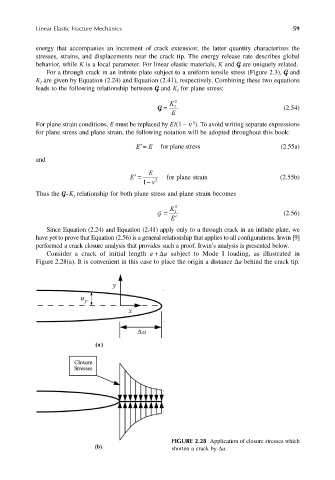
Consider a crack of initial length a +∆a subject to Mode I loading, as illustrated in
Figure 2.28(a). It is convenient in this case to place the origin a distance ∆a behind the crack tip.
FIGURE 2.28 Application of closure stresses which
shorten a crack by ∆a.