
Page 82 - T. Anderson-Fracture Mechanics - Fundamentals and Applns.-CRC (2005)
P. 82
1656_C02.fm Page 62 Thursday, April 14, 2005 6:28 PM
62 Fracture Mechanics: Fundamentals and Applications
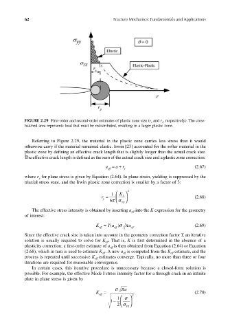
FIGURE 2.29 First-order and second-order estimates of plastic zone size (r y and r p , respectively). The cross-
hatched area represents load that must be redistributed, resulting in a larger plastic zone.
Referring to Figure 2.29, the material in the plastic zone carries less stress than it would
otherwise carry if the material remained elastic. Irwin [23] accounted for the softer material in the
plastic zone by defining an effective crack length that is slightly longer than the actual crack size.
The effective crack length is defined as the sum of the actual crack size and a plastic zone correction:
a eff a =+ r y (2.67)
where r for plane stress is given by Equation (2.64). In plane strain, yielding is suppressed by the
y
triaxial stress state, and the Irwin plastic zone correction is smaller by a factor of 3:
K
1
r = 6πσ YS 2 (2.68)
I
y
The effective stress intensity is obtained by inserting a into the K expression for the geometry
eff
of interest:
K eff Y a= ( eff a )σπ eff (2.69)
Since the effective crack size is taken into account in the geometry correction factor Y, an iterative
solution is usually required to solve for K . That is, K is first determined in the absence of a
eff
plasticity correction; a first-order estimate of a is then obtained from Equation (2.64) or Equation
eff
(2.68), which in turn is used to estimate K . A new a is computed from the K estimate, and the
eff
eff
eff
process is repeated until successive K estimates converge. Typically, no more than three or four
eff
iterations are required for reasonable convergence.
In certain cases, this iterative procedure is unnecessary because a closed-form solution is
possible. For example, the effective Mode I stress intensity factor for a through crack in an infinite
plate in plane stress is given by
σπ a
K eff = 2 (2.70)
1 − 1 σ
2 σ YS 