
Page 181 - From Smart Grid to Internet of Energy
P. 181
Power line communication technologies in smart grids Chapter 4 157
inverter is employed to generate three-phase AC line voltages. PI regulator and
phase disposition sinusoidal pulse width modulation (PD-SPWM) algorithm are
employed to manage the MLI. Each solar plant contains 150 photovoltaic (PV)
modules where each PV module with 170 W power are designed with respect to
Sharp NE-170UC1 PV panel [95]. The designed buck converters to feed diode
clamped MLI system regulate the generated electricity by the solar plants.
The buck converters are managed by employing P&O MPPT algorithm that
provides to obtain maximum power and regulated DC output voltage. The trans-
mission and distribution section of designed microgrid is modeled by using a
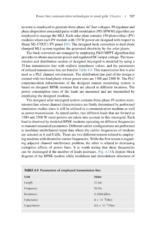
25 km transmission line with realistic impedance values, and the parameters
of utilized transmission line are listed in Table 4.9. This transmission line is also
used as a PLC channel environment. The distribution line part of the design is
created with two load plants whose power rates are 1500 and 2500 W. The PLC
communication infrastructure of the designed remote monitoring system is
based on designed BPSK modems that are placed in different locations. The
power consumption rates of the loads are measured and are transmitted by
employing the designed modems.
The designed solar microgrid system contains three-phase PI section trans-
mission line whose channel characteristics are firstly determined by performed
simulation studies since it will be utilized as a communication medium as well
as power transmission. As stated earlier, two different loads that are formed as
1500 and 2500 W rated powers are taken into account in this microgrid. Each
load is observed by modeled BPSK modems operating on different frequencies
to transmit measured parameters. Different carrier configurations are performed
to modulate multichannel input data where the carrier frequencies of modems
are selected as 6 and 8 kHz. There are two different reasons related to employ-
ing modems with dissimilar carrier frequencies. While the first reason is regard-
ing adjacent channel interference problem, the other is related to decreasing
corruptive effects of power lines. It is worth noting that these frequencies
can be rearranged if the number of loads increases. Fig. 4.15A depicts block
diagram of the BPSK modem while modulator and demodulator structures of
TABLE 4.9 Parameters of employed transmission line
Unit Value
Length 25 km
Frequency 50 Hz
Resistance 0.2568 Ω/km
7
Inductance 4 10 H/km
Capacitance 8.6 10 9 F/km