
Page 186 - From Smart Grid to Internet of Energy
P. 186
Power line communication technologies in smart grids Chapter 4 161
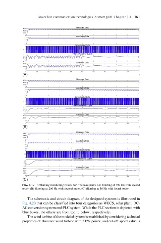
FIG. 4.17 Obtaining monitoring results for first load plant, (A) filtering at 400 Hz with second
order, (B) filtering at 200 Hz with second order, (C) filtering at 50 Hz with fourth order.
The schematic and circuit diagram of the designed systems is illustrated in
Fig. 4.20 that can be classified into four categories as WECS, solar plant, DC-
AC conversion system and PLC system. While the PLC section is depicted with
blue boxes, the others are from top to below, respectively.
The wind turbine of the modeled system is established by considering technical
properties of Hummer wind turbine with 3 kW power, and cut-off speed value is