
Page 190 - From Smart Grid to Internet of Energy
P. 190
Power line communication technologies in smart grids Chapter 4 165
FIG. 4.23 Output voltage waveforms of WECS, solar plant, and DC bus.
which is illustrated in Fig. 4.23. Afterwards, the DC bus voltage is fed to the
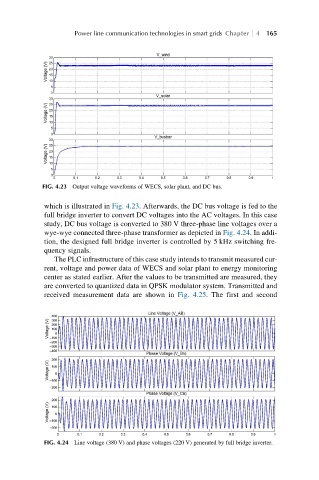
full bridge inverter to convert DC voltages into the AC voltages. In this case
study, DC bus voltage is converted to 380 V three-phase line voltages over a
wye-wye connected three-phase transformer as depicted in Fig. 4.24. In addi-
tion, the designed full bridge inverter is controlled by 5 kHz switching fre-
quency signals.
The PLC infrastructure of this case study intends to transmit measured cur-
rent, voltage and power data of WECS and solar plant to energy monitoring
center as stated earlier. After the values to be transmitted are measured, they
are converted to quantized data in QPSK modulator system. Transmitted and
received measurement data are shown in Fig. 4.25. The first and second
FIG. 4.24 Line voltage (380 V) and phase voltages (220 V) generated by full bridge inverter.