
Page 75 - Fundamentals of Communications Systems
P. 75
Signals and Systems Review 2.27
(b)
πt
Asin 0 ≤ t ≤ T p
T p
x(t) = (2.87)
0 elsewhere
and give the value of A such that E u = 1. Compute the 40-dB relative band-
width, B 40 , of each signal.
Problem 2.6. This problem is an example of a problem which is best solved with
the help of a computer. The signal x(t) is passed through an ideal lowpass filter
of bandwidth B/T p Hz. For the signals given in Problem 2.5 with unit energy
make a plot of the output energy versus B.
Hint: Recall the trapezoidal rule from calculus to approximately compute this
energy.
Problem 2.7. This problem uses signal and system theory to compute the output
of a simple memoryless nonlinearity. An amplifier is an often used device in com-
munication systems and is simply modeled as an ideal memoryless system, i.e.,
y(t) = a 1 x(t)
This model is an excellent model until the signal levels get large then non-
linear things start to happen, which can produce unexpected changes in the
output signals. These changes often have a significant impact in a communica-
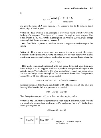
tion system design. As an example of this characteristic consider the system in
Figure 2.11 with the following signal model
x(t) = b 1 cos(200000πt) + b 2 cos(202000πt)
the ideal bandpass filter has a bandwidth of 10 kHz centered at 100 kHz, and
the amplifier has the following memoryless model
3
y(t) = a 1 x(t) + a 3 x (t)
Give the system output, z(t), as a function of a 1 , a 3 , b 1 , and b 3 .
Problem 2.8. (PD) A nonlinear device that is often used in communication systems
is a quadratic memoryless nonlinearity. For such a device if x(t) is the input
the output is given as
2
y(t) = ax(t) + bx (t)
xt() yt() zt()
Amplifier Ideal BPF
Figure 2.11 The system diagram
for Problem 2.7.