
Page 226 - Fundamentals of Computational Geoscience Numerical Methods and Algorithms
P. 226
8.4 Test and Application Examples of the Particle Simulation Method 217
to gravity. In order to simulate the slip of the underlying fault, the right half of the
bottom is fixed, while the left half of the bottom is allowed to move in the direction
that is parallel to the underlying fault plane in the rigid basement.
As we mentioned in the previous section, the second numerical simulation issue
associated with the distinct element method is an inherent issue, which is caused
by using the explicit dynamic relaxation method to solve a quasi-static problem.
Although the problem related to this issue cannot be completely solved at this stage,
an expedient measure is strongly recommended to carry out a particle-size sensitiv-
ity analysis of at least two different models, which have the same initial geometry
but different total numbers of particles, to confirm the particle simulation result of
a large-scale quasi-static system. For this purpose, the same problem as considered
above is simulated using 8000 particles, so that the total number of particles used in
this simulation is twice that used in the previous simulation. For ease of discussion,
the previous model of 4000 particles is called the 4000-particle model, while the
model of 8000 particles is defined as the 8000-particle model. For the 8000-particle
model, the maximum and minimum radii of particles are approximately 21.55 m
and 14.37 m, resulting in an average radius of 17.96 m. Note that the average radius
of particles used in the 4000-particle model is 25.4 m.
It needs to be pointed out that in theory, the smallest particle size of a particle
model is related directly to the material fracture toughness (Potyondy and Cundall
2004), especially under mixed compressive-extensile conditions. In the case of mod-
eling damage processes for which macroscopic cracks form, the smallest particle
size and model properties should be chosen to match the material fracture toughness
as well as the unconfined compressive strength. However, it was also found that the
formation of a failure plane and secondary macro-cracks may be independent of par-
ticle size under mixed compressive-shear conditions (Potyondy and Cundall 2004),
which are those that we consider in this study. Nevertheless, in order to test whether
or not the formation of macroscopic cracks is dependent on the smallest particle
size, it is recommended that a particle-size sensitivity analysis of at least two dif-
ferent models, which have the same geometry but different smallest particle sizes,
be carried out to confirm the particle simulation result of a large-scale quasi-static
system.
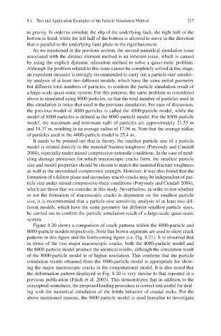
Figure 8.20 shows a comparison of crack patterns within the 4000-particle and
8000-particle models respectively. Note that brown segments are used to show crack
patterns in this figure and the forthcoming figure (i.e. Fig. 8.21). It is observed that
in terms of the two major macroscopic cracks, both the 4000-particle model and
the 8000-particle model produce the identical results, although the simulation result
of the 8000-particle model is of higher resolution. This confirms that the particle
simulation results obtained from the 4000-particle model is appropriate for show-
ing the major macroscopic cracks in the computational model. It is also noted that
the deformation pattern displayed in Fig. 8.20 is very similar to that reported in a
previous publication (Finch et al. 2003). This demonstrates that in addition to the
conceptual soundness, the proposed loading procedure is correct and useful for deal-
ing with the numerical simulation of the brittle behavior of crustal rocks. For the
above-mentioned reasons, the 8000-particle model is used hereafter to investigate