
Page 225 - Fundamentals of Computational Geoscience Numerical Methods and Algorithms
P. 225
216 8 Spontaneous Crack Generation Problems in Large-Scale Geological Systems
8.4.4 Particle Simulation of the Faulting Process Using
the Proposed Particle Method
The problem associated with the crustal fault-propagation folding above rigid base-
ment blocks is considered to illustrate the particle simulation of spontaneous crack
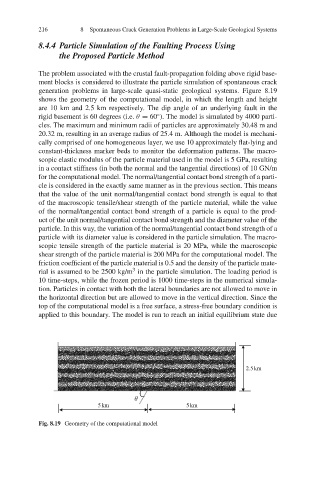
generation problems in large-scale quasi-static geological systems. Figure 8.19
shows the geometry of the computational model, in which the length and height
are 10 km and 2.5 km respectively. The dip angle of an underlying fault in the
◦
rigid basement is 60 degrees (i.e. θ = 60 ). The model is simulated by 4000 parti-
cles. The maximum and minimum radii of particles are approximately 30.48 m and
20.32 m, resulting in an average radius of 25.4 m. Although the model is mechani-
cally comprised of one homogeneous layer, we use 10 approximately flat-lying and
constant-thickness marker beds to monitor the deformation patterns. The macro-
scopic elastic modulus of the particle material used in the model is 5 GPa, resulting
in a contact stiffness (in both the normal and the tangential directions) of 10 GN/m
for the computational model. The normal/tangential contact bond strength of a parti-
cle is considered in the exactly same manner as in the previous section. This means
that the value of the unit normal/tangential contact bond strength is equal to that
of the macroscopic tensile/shear strength of the particle material, while the value
of the normal/tangential contact bond strength of a particle is equal to the prod-
uct of the unit normal/tangential contact bond strength and the diameter value of the
particle. In this way, the variation of the normal/tangential contact bond strength of a
particle with its diameter value is considered in the particle simulation. The macro-
scopic tensile strength of the particle material is 20 MPa, while the macroscopic
shear strength of the particle material is 200 MPa for the computational model. The
friction coefficient of the particle material is 0.5 and the density of the particle mate-
3
rial is assumed to be 2500 kg/m in the particle simulation. The loading period is
10 time-steps, while the frozen period is 1000 time-steps in the numerical simula-
tion. Particles in contact with both the lateral boundaries are not allowed to move in
the horizontal direction but are allowed to move in the vertical direction. Since the
top of the computational model is a free surface, a stress-free boundary condition is
applied to this boundary. The model is run to reach an initial equilibrium state due
2.5 km
θ
5 km 5 km
Fig. 8.19 Geometry of the computational model