
Page 142 - Fundamentals of Gas Shale Reservoirs
P. 142
122 PETROPHYSICAL EVALUATION OF GAS SHALE RESERVOIRS
15
Mesopore Macropore
Incremental PV (%pu) 10 5 Micropore Gas adsorption
MICP
0
1 10 100 1,000
Pore width (nm)
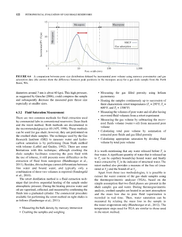
FIGURE 6.6 A comparison between pore size distribution defined by incremental pore volume using mercury porosimetry and gas
adsorption data (the arrows show the difference between peak positions in the mesopore area) for a gas shale sample from the Perth
Basin, WA.
diameters around 3 nm is about 60 kpsi. This high pressure, • Measuring the gas filled porosity using helium
as suggested by Giesche (2006), could compress the sample pycnometry
and subsequently decrease the measured pore throat size • Heating the samples continuously up to succession of
especially at smaller sizes. three characteristic retort temperatures (T = 250°F, T =
1
2
600°F, and T = 1300°F)
3
6.3.2 Fluid Saturation Measurement • Measuring the volumes of pore water and oil after having
recovered fluid volumes from a retort experiment
There are two common methods for fluid extraction used • Measuring the gas volume by subtracting the recov
by commercial labs in conventional reservoirs: Dean Stark ered fluids volume (water + oil) from measured pore
and the retort method. Both methods are documented in volume
the recommended practice 40 (API, 1998). These methods
can be used for gas shale; however, they are performed on • Calculating total pore volume by summation of
the crushed shale samples. The technique used by the Gas extracted pore fluids and gas filled porosity
Research Institute (GRI) to measure water and hydro • Calculating appropriate saturation by dividing fluid
carbon saturation is by performing Dean Stark method volume by total pore volume
with toluene (Luffel and Guidry, 1992). There are some
limitations with this technique; although crushing the It is worth mentioning that any water released before T is
1
shale samples facilitates removing the pore fluid with free water. A significant quantity of water that is released up
the use of toluene, it still presents some difficulties in the to T can be capillary‐bound/clay‐bound water and finally
2
extraction of fluid from nanopores (Handwerger et al., water extracted by T is the indicator of structural water. The
3
2011). Besides, this technique cannot differentiate between retort method also provides a measure of the free oil (mea
free water and bound water, and typically only a sured at T ) and the bound oil at T .
3
2
combination of these two volumes is reported (Sondergeld Apart from these two methodologies, it is possible to
et al., 2010). extract the water content of the gas shale samples using
The retort distillation method is a fluid extraction tech the thermogravimetric analyzer (TGA), based on the
nique that involves sequential heating of the sample under simple assumption that two fluid phases are present in the
atmospheric pressure. During the heating process water and shale sample: gas and water. During thermogravimetric
oil are vaporized, collected, and measured by condensing the analysis, crushed samples are heated in an inert atmosphere
fluids into a graduated cylinder. The commercial procedure and the mass loss due to pore fluid vaporization is
available for performing the retort method on tight shales is recorded in real time. Then, water saturation can be
as follows (Handwerger et al.; 2011): measured by relating the mass loss in the sample to
the water evaporation only (Handwerger et al., 2012). The
• Measuring the bulk density by mercury immersion temperature steps used for TGA are similar to those used
• Crushing the samples and weighing in the retort method.