Page 283 - Fundamentals of Gas Shale Reservoirs
P. 283

CANISTER DESORPTION TEST  263


                                               Valve 1    P c    Valve 2


                                                                            V d


                                                         V p

                                        V r


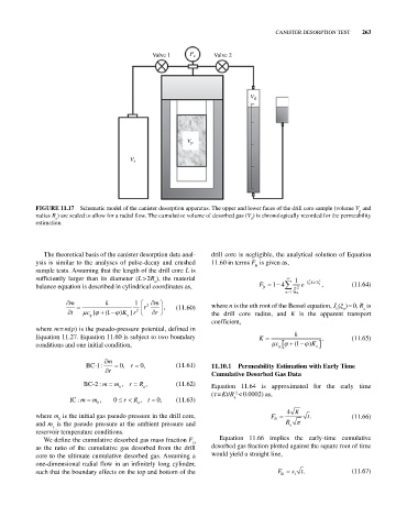
            FIGURE 11.17  Schematic model of the canister desorption apparatus. The upper and lower faces of the drill core sample (volume V  and
                                                                                                             p
            radius R ) are sealed to allow for a radial flow. The cumulative volume of desorbed gas (V ) is chronologically recorded for the permeability
                                                                            d
                  a
            estimation.


              The theoretical basis of the canister desorption data anal-  drill core is negligible, the analytical solution of Equation
            ysis is similar to the analyses of pulse‐decay and crushed   11.60 in terms F  is given as,
                                                                              R
            sample tests. Assuming that the length of the drill core L is
            sufficiently larger than its diameter (L > 2R ), the material                 1   2  /  2
                                               a
            balance equation is described in cylindrical coordinates as,       F D  14    2  e  n  Kt R a  ,  (11.64)
                                                                                       n 1  n
                      m          k        1    m
                                            r 2   ,   (11.60)    where n is the nth root of the Bessel equation, J (ξ ) = 0, R  is
                                                                                                      0
                                                                                                              a
                                                                                                        n
                      t    c [   (1  ) K r ]  2  r               the drill core radius, and  K is the apparent transport
                                       a
                            g
                                                                 coefficient,
            where m = m(p) is the pseudo‐pressure potential, defined in
            Equation 11.27. Equation 11.60 is subject to two boundary          K          k       .        (11.65)
            conditions and one initial condition,                                   c g   (1  ) K a
                                 m
                           BC-1:     0, r   , 0       (11.61)    11.10.1  Permeability Estimation with Early Time
                                  r
                                                                 Cumulative Desorbed Gas Data
                          BC-2: m  m  , r  R  ,       (11.62)
                                     e      a                    Equation 11.64 is approximated for the early time
                                                                 (τ = Kt/R  < 0.0002) as,
                                                                        2
                      IC : m  m 0 ,  0  r  R a , t  , 0  (11.63)       a
                                                                                       4  K
            where m  is the initial gas pseudo pressure in the drill core,         F D       t.            (11.66)
                   0
            and m  is the pseudo pressure at the ambient pressure and                  R a
                 e
            reservoir temperature conditions.
              We define the cumulative desorbed gas mass fraction F    Equation 11.66 implies the early‐time cumulative
                                                           D
            as the ratio of the cumulative gas desorbed from the drill   desorbed gas fraction plotted against the square root of time
            core to the ultimate cumulative desorbed gas. Assuming a   would yield a straight line,
            one‐dimensional radial flow in an infinitely long cylinder,
            such that the boundary effects on the top and bottom of the              F D  s 1  t.          (11.67)
   278   279   280   281   282   283   284   285   286   287   288