
Page 280 - Fundamentals of Gas Shale Reservoirs
P. 280
260 GAS TRANSPORT PROCESSES IN SHALE
1
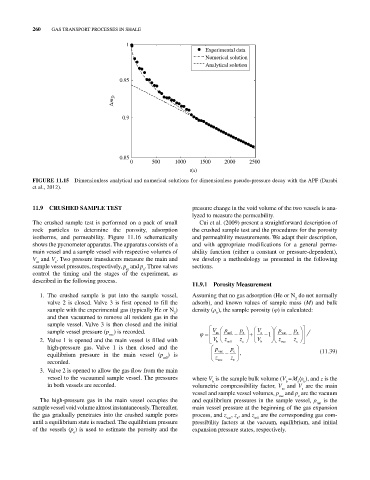
Experimental data
Numerical solution
Analytical solution
0.95
m D
0.9
0.85
0 500 1000 1500 2000 2500
t(s)
FIGURE 11.15 Dimensionless analytical and numerical solutions for dimensionless pseudo‐pressure decay with the APF (Darabi
et al., 2012).
11.9 CRUSHED SAMPLE TEST pressure change in the void volume of the two vessels is ana-
lyzed to measure the permeability.
The crushed sample test is performed on a pack of small Cui et al. (2009) present a straightforward description of
rock particles to determine the porosity, adsorption the crushed sample test and the procedures for the porosity
isotherms, and permeability. Figure 11.16 schematically and permeability measurements. We adapt their description,
shows the pycnometer apparatus. The apparatus consists of a and with appropriate modifications for a general perme-
main vessel and a sample vessel with respective volumes of ability function (either a constant or pressure‐dependent),
V and V . Two pressure transducers measure the main and we develop a methodology as presented in the following
m s
sample vessel pressures, respectively, p and p . Three valves sections.
m s
control the timing and the stages of the experiment, as
described in the following process.
11.9.1 Porosity Measurement
1. The crushed sample is put into the sample vessel, Assuming that no gas adsorption (He or N do not normally
2
valve 2 is closed. Valve 3 is first opened to fill the adsorb), and known values of sample mass (M) and bulk
sample with the experimental gas (typically He or N ) density (ρ ), the sample porosity (φ) is calculated:
2 b
and then vacuumed to remove all resident gas in the
sample vessel. Valve 3 is then closed and the initial
sample vessel pressure (p ) is recorded. V m p m0 p e V s p vac p e
vac 1
2. Valve 1 is opened and the main vessel is filled with V b z m0 z e V b z vac z e
high‐pressure gas. Valve 1 is then closed and the p vac p e (11.39)
equilibrium pressure in the main vessel (p ) is ,
m0 z z
recorded. vac e
3. Valve 2 is opened to allow the gas flow from the main
vessel to the vacuumed sample vessel. The pressures where V is the sample bulk volume (V = M /ρ ), and z is the
b
b
s
b
in both vessels are recorded. volumetric compressibility factor, V and V are the main
s
m
vessel and sample vessel volumes, p and p are the vacuum
vac
e
The high‐pressure gas in the main vessel occupies the and equilibrium pressures in the sample vessel, p is the
m0
sample vessel void volume almost instantaneously. Thereafter, main vessel pressure at the beginning of the gas expansion
the gas gradually penetrates into the crushed sample pores process, and z , z , and z are the corresponding gas com-
m0
vac
e
until a equilibrium state is reached. The equilibrium pressure pressibility factors at the vacuum, equilibrium, and initial
of the vessels (p ) is used to estimate the porosity and the expansion pressure states, respectively.
e