
Page 281 - Fundamentals of Gas Shale Reservoirs
P. 281
CRUSHED SAMPLE TEST 261
P where A = 3M /(ρ R ) is the total surface area of the spherical
b
a
s
s
P m crushed particles, m is the initial pseudo pressure of the gas
0
in sample pores, and m is the pseudo pressure of the void
P e volume of the main and sample vessels at the beginning of
c0
P P
P m s s gas penetration into the crushed sample pores.
t
The analytical solution for pseudo pressure m(p) in the
Valve 1 Valve 2 Valve 3 void volume of the main and sample vessels may be found by
Sample vessel assuming the permeability k and viscosity‐volumetric com-
Main vessel (V s ) pressibility µc are constant. The constant permeability
g
(V m ) assumption is reasonable because the pseudo pressure decline
after the initial gas expansion into the sample vessel is small.
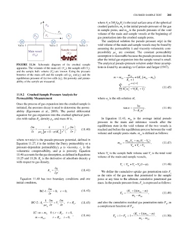
FIGURE 11.16 Schematic diagram of the crushed sample The analytical pseudo‐pressure solution under these assump-
apparatus. The volumes of the main cell (V ), the sample cell (V ), tions is found by an analogy to Carslaw and Jaegar (1947),
s
m
and the sample bulk volume (V ) are known. Using the pressure
b
histories of the main cell and the sample cell (p and p ) and the m
m
s
equilibrium pressure of the two cells (p ), the porosity and perme- m m c0 K c0 1 6 Km c0 m 0
c
e
ability of the sample are measured. c
2
e K n / t R a 2
2 2 , (11.45)
n 1 K c n 9 K c 1
11.9.2 Crushed Sample Pressure Analysis for
Permeability Measurement where α is the nth solution of,
n
Once the process of gas expansion into the crushed sample is
initiated, the pressure decay is used to determine the perme- tan 3 . (11.46)
ability (Egermann et al., 2005). The partial differential 3 K c 2
equation for gas expansion into the crushed spherical parti-
cles with radius R , density ρ , and mass M is, In Equation 11.45, m is the average initial pseudo
a b c0
pressure in the main and reference vessels after the
equilibrium state in the void volume of the two vessels is
m k 1 m
r 2 , (11.40) reached and before the equilibrium process between the void
t c (1 ) K r 2 r
g a volume and sample pores starts. m is defined as follows:
c0
where m = m(p) is the pseudo‐pressure potential, defined in mV mV V )
(
Equation 11.27, k is the (either the Darcy permeability or a m c0 m0 V m V 0 V s b , (11.47)
pressure‐dependent permeability), μ is viscosity, c is the m s b
g
volumetric compressibility, and φ is porosity. Equation
11.40 accounts for the gas desorption, as defined in Equations where V is the sample bulk volume and V is the total void
b
c
11.25 and 11.26. K is the derivative of adsorbate density q volume of the main and sample vessels,
a
with respect to gas density,
V V V V (1 . ) (11.48)
c m s b
q
K a . (11.41) We define the cumulative uptake gas penetration ratio F
u
as the ratio of the gas mass that penetrated to the sample
Equation 11.40 has two boundary conditions and one pores at any time to the ultimate cumulative penetrated gas
initial condition, mass. In the pseudo pressure form, F is expressed as follows:
U
m
BC-1: 0, r , 0 (11.42) ( K c 1 )( m c0 m)
r F U , (11.49)
m 0 m c0
k m m
BC-2: A V , r R , (11.43) and also the cumulative residual gas penetration ratio F , as
s
c r c t a R
g a complement function of F ,
U
IC : m m 0 r R , t , 0 ( K 1)( m m)
0 a , (11.44) F 1 F 1 c c0 . (11.50)
m m , r R , t , 0 R U
c0 a m 0 m c0