Page 276 - Fundamentals of Gas Shale Reservoirs
P. 276

256   GAS TRANSPORT PROCESSES IN SHALE

            by the total volume of TOC in the sample. Equation 11.21 is   Etminan et al. (2014) used Equation 11.23 to model pulse
            the solution of partial differential equation (Eq. 11.17) with   pressure decay data to determine the diffusion coefficient of
            the defined boundary and initial conditions in Equations   methane in kerogen material, D. If D is known then, Equation
            11.18–11.20 (Crank, 1979).                           11.23 can be used to determine the mass of diffusing gas at
                                                                 certain reservoir conditions.
                             4     1      (2 n 1 )
                   ,
                  (
                Cz t)  C 1            sin         z
                         *
                 g       g
                               n 2 n 1       2 h                 11.8  PULSE‐DECAY PERMEAbILITY
                                1
                               (2 n 1 ) 2  2 D                   MEASUREMENT TEST
                          exp             t  .        (11.21)
                                   4h 2
                                                                 The pulse‐decay experiment is primarily developed for the
              An integration of Equation 11.21 over the volume of   measurement of gas permeability of the tight porous media
              kerogen volume is needed to find the mass of gas dissolved.  (Aronofsky, 1954; Aronofsky et al., 1959; Bruce et al., 1952;
                                                                 Wallick and Aronofsky, 1954). The pulse‐decay experiment
                                   zh                            has applications in petroleum engineering as well as in other
                         m     t ()  Cz t,Adz.        (11.22)    scientific and engineering fields such as hydrology (Finsterle
                                         )
                                       (
                           gDiff      g
                                   z 0                           and Najita, 1997), rock physics (Walder and Nur, 1986), and
                                                                 pressure vessel technology (Lasseux et al., 2011).
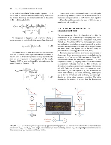
              In Equation 11.22, A is the area open to molecular diffu-  The pulse‐decay experiment involves the measurement of
            sion, and h is defined as the depth of diffusion. Evaluation of   the pressure‐decay response to a pressure perturbation at the
            the area open to diffusion (A) and the average depth of diffu-  upstream face of low‐permeability core sample. Figure 11.13
            sion (h) are important in interpretation of the results.   schematically shows the pulse‐decay apparatus.  The core
            Equation 11.23 is what is obtained by integration over the   sample with volume v  is tightly held in a core holder under
                                                                                  p
            spatial domain in Equation 11.21.                    a hydrostatic confining pressure  p .  The upstream and
                                                                                               c
                                                                   downstream core faces are set to communicate with two ves-
                               *
                           8 AC h     1                          sels with finite gas volumes: namely, the upstream vessel
                 m gDiff  t   2 g         2                      with volume V  and initial pressure p , and the downstream
                                                                            u
                                                                                              ui
                                 n 1  2 n 1                      vessel with volume V  and initial pressure p . Subscripts d
                                                                                                     di
                                                                                  d
                                    2 n 1  2  2 D                and u denote downstream and upstream, and subscript i
                           1 exp               t  .   (11.23)    denotes an initial‐value boundary condition.  The initial
                                       4 h 2
                                                                 pressure in the upstream is greater than the downstream.
                              P u                           P                      P d

                                                                     t
                                         t                                                    t
                                                                 P
                                   P u                                                  P d


                                 Upstream    V2                                     Downstream
                                  vessel                   Core sample, V p            vessel
                                   V u                                                  V d
                                                          Con ned pressure
                                      V1                                            V3
                                                            V4
                                                  Con ning
                                                   pressure            P c

            FIGURE 11.13  Schematic diagram of a pulse‐decay apparatus showing upstream and downstream reservoir volumes and instantaneous
            pressures are (V , p ) and (V , p ). Core sample pore volume (V ) is under a confining pressure of p ; the temporal pressure difference across
                                                                                   c
                          u
                       u
                                d
                                                         p
                                  d
            the core sample ∆p = p  − p  is measured during the test.
                            u  d
   271   272   273   274   275   276   277   278   279   280   281