
Page 139 - Fundamentals of Magnetic Thermonuclear Reactor Design
P. 139
Superconducting Magnet Systems Chapter | 5 123
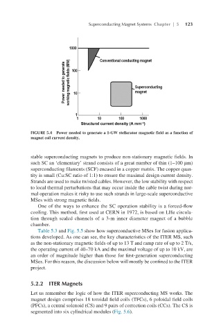
FIGURE 5.4 Power needed to generate a 1-GW stellarator magnetic field as a function of
magnet coil current density.
stable superconducting magnets to produce non-stationary magnetic fields. In
such SC an ‘elementary’ strand consists of a great number of thin (1–100 µm)
superconducting filaments (SCF) encased in a copper matrix. The copper quan-
tity is small (Cu:SC ratio of 1:1) to ensure the maximal design current density.
Strands are used to make twisted cables. However, the low stability with respect
to local thermal perturbations that may occur inside the cable twist during nor-
mal operation makes it risky to use such strands in large-scale superconductive
MSes with strong magnetic fields.
One of the ways to enhance the SC operation stability is a forced-flow
cooling. This method, first used at CERN in 1972, is based on LHe circula-
tion through sealed channels of a 3-m inner diameter magnet of a bubble
chamber.
Table 5.3 and Fig. 5.5 show how superconductive MSes for fusion applica-
tions developed. As one can see, the key characteristics of the ITER MS, such
as the non-stationary magnetic fields of up to 13 T and ramp rate of up to 2 T/s,
the operating current of 40–70 kA and the maximal voltage of up to 10 kV, are
an order of magnitude higher than those for first-generation superconducting
MSes. For this reason, the discussion below will mostly be confined to the ITER
project.
5.2.2 ITER Magnets
Let us remember the logic of how the ITER superconducting MS works. The
magnet design comprises 18 toroidal field coils (TFCs), 6 poloidal field coils
(PFCs), a central solenoid (CS) and 9 pairs of correction coils (CCs). The CS is
segmented into six cylindrical modules (Fig. 5.6).