
Page 142 - Fundamentals of Magnetic Thermonuclear Reactor Design
P. 142
Superconducting Magnet Systems Chapter | 5 125
FIGURE 5.5 Outlines of middle turns of toroidal field coils in different tokamak generations.
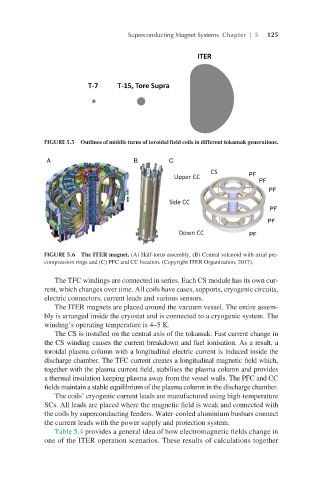
FIGURE 5.6 The ITER magnet. (A) Half-torus assembly, (B) Central solenoid with axial pre-
compression rings and (C) PFC and CC location. (Copyright ITER Organization, 2017).
The TFC windings are connected in series. Each CS module has its own cur-
rent, which changes over time. All coils have cases, supports, cryogenic circuits,
electric connectors, current leads and various sensors.
The ITER magnets are placed around the vacuum vessel. The entire assem-
bly is arranged inside the cryostat and is connected to a cryogenic system. The
winding’s operating temperature is 4–5 K.
The CS is installed on the central axis of the tokamak. Fast current change in
the CS winding causes the current breakdown and fuel ionisation. As a result, a
toroidal plasma column with a longitudinal electric current is induced inside the
discharge chamber. The TFC current creates a longitudinal magnetic field which,
together with the plasma current field, stabilises the plasma column and provides
a thermal insulation keeping plasma away from the vessel walls. The PFC and CC
fields maintain a stable equilibrium of the plasma column in the discharge chamber.
The coils’ cryogenic current leads are manufactured using high-temperature
SCs. All leads are placed where the magnetic field is weak and connected with
the coils by superconducting feeders. Water-cooled aluminium busbars connect
the current leads with the power supply and protection system.
Table 5.4 provides a general idea of how electromagnetic fields change in
one of the ITER operation scenarios. These results of calculations together