
Page 144 - Fundamentals of Magnetic Thermonuclear Reactor Design
P. 144
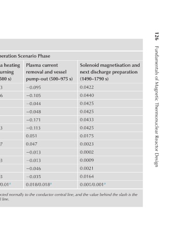
126     Fundamentals of Magnetic Thermonuclear Reactor Design


                        Solenoid magnetisation and  next discharge preparation   (1490–1790 s)  0.0422  0.0440  0.0425  0.0425  0.0433  0.0425  0.0175  0.0023  0.0002  0.0009  0.0021  0.0164  0.001/0.001 a


                     Operation Scenario Phase  Plasma current  Plasma heating   removal and vessel  and burning   pump-out (500–975 s) (100–500 s)  −0.095  −0.073  −0.105  −0.066  0.006  −0.044  −0.048  0.006  −0.171  0.010  −0.113  −0.083  0.051  0.053  0.047  −0.007  0.005  −0.013  −0.013  −0.003  −0.046  0.003  −0.035  −0.003  0.018/0.018


                  TABLE 5.4 Magnetic Field Change Rates in ITER Coils (T/s)
                        Plasma   current ramp   (1.5–100 s)  −0.346  −0.364  −0.457  −0.453  −0.271  −0.140  0.110  0.061  0.040  0.029  0.073  0.034  0.04/0.05 a


                        Breakdown and   plasma ignition   initial stage (0–1.5 s)  −0.853  −1.530  −1.070  −1.260  −1.986  −1.960  −0.997  −0.713  0.212  −0.156  −0.724  −0.474  0.45/0.47 a rate of change of the magnetic field component directed parallel to the conductor central line.


                      Maximum   Field (T)   (current,   (kA))  13(40)  6 (46)  4  4  4  5  6 (46)  11.8


                                CS (CS3U)  CS (CS2U)  CS (CS1U)  CS (CS1L)  CS (CS2L)  CS (CS3L)  PFC (PF1)  PFC (PF2)  PFC (PF3)  PFC (PF4)  PFC (PF5)  PFC (PF6)  TFC (TF)

                             Coil