
Page 236 - Fundamentals of Magnetic Thermonuclear Reactor Design
P. 236
First Wall Components Chapter | 7 217
the toroid helically are bound to hit the diaphragms and neutralise, and their
lifetime is much shorter than that of the plasma ions. The diaphragms also pro-
tect the walls against ‘runaway’ electrons. The wall reacts and absorbs all other
energy flows. Because of the low intensity of those flows and the small thermal
deformations, the 1st-Gen tokamak FW and vacuum boundary performed the
same functions.
With plasma discharge getting more powerful and longer, the idea was, first,
to curtain off the wall by heat-accumulating elements, and then to chill it down
using forced water cooling.
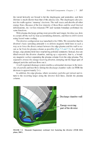
The divertor configuration was launched in the 1980s. We remember that the
divertor’s basic operating principle is to deform magnetic field lines in such a
way as to force the direct contact between the edge plasma and the wall to oc-
cur as far from the plasma column as possible (Figs 7.2 and 7.3). In a divertor
design, edge plasma field lines stop having poloidal symmetry. Instead, they are
tilted towards the divertor chamber, making up a separatrix, that is, a bound-
ary magnetic surface separating the plasma column from the edge plasma. The
separatrix crosses the energy-receiving divertor, dumping out the larger part of
charged particles and heat flows on it.
A well-regulated drainage system enables a substantial decrease in the inten-
sity of particle and heat flows hitting the discharge chamber walls (in ITER the
decrease is approximately 2×).
In addition, the edge plasma, where secondary particles get ionised and re-
turn to the receiving target along the divertor field lines, shields the plasma
column.
FIGURE 7.2 Tokamak fragmentary sectional view featuring the divertor (ITER EDA
phase, 2001).