
Page 233 - Fundamentals of Magnetic Thermonuclear Reactor Design
P. 233
214 Fundamentals of Magnetic Thermonuclear Reactor Design
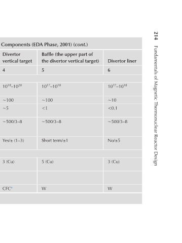
Divertor liner 6 10 17 –10 18 ∼10 <0.1 ∼500/3–8 No/±5 3 (Cu) W
Baffle (the upper part of the divertor vertical target) 5 10 17 –10 18 ∼100 <1 ∼500/3–8 Short term/±1 5 (Cu) W
TABLE 7.1 Expected Operating Conditions of the ITER In-Chamber Components (EDA Phase, 2001) (cont.)
Divertor vertical target 4 10 18 –10 20 ∼100 ∼5 ∼500/3–8 Yes/± (1–3) 3 (Cu) CFC a
Start-up limiter 3 10 17 –10 18 ∼100 0.5 2300/2 Yes/±0.5 0.78 4.6 (Be) 7.3 (Cu) Be
First wall 2 10 16 –10 17 ∼100 < 0.5 4600/- Short term/±2 0.78 4.6 (Be) 7.3 (Cu) Be
Operation conditions 1 Quasi-stationary particleflux parameters Ion/c-x neutral flux density (cm −2 s −1 ) Particle flow energy (eV) Expected surface erosion rate (mm/year 1 ) Projected hours of operation till replacement/tolerable number of replacements Immediate contact with plasma/ limited position er