
Page 231 - Fundamentals of Magnetic Thermonuclear Reactor Design
P. 231
First Wall Components Chapter | 7 213
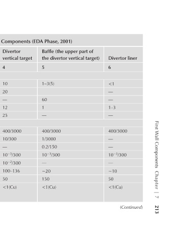
Divertor liner 6 <1 — — 1–3 — 400/3000 — — 10 −3 /300 — ∼10 50 <1(Cu) (Continued)
Baffle (the upper part of the divertor vertical target) 5 1–3(5) 60 1 — 400/3000 1/3000 0.2/150 10 −3 /300 — ∼20 150 <1(Cu)
TABLE 7.1 Expected Operating Conditions of the ITER In-Chamber Components (EDA Phase, 2001)
Divertor vertical target 4 10 20 — 12 25 400/3000 10/300 — 10 −3 /300 10 −2 /300 100–136 50 <1(Cu)
Start-up limiter 3 0.5 4–8 — 1 — 400/3000 30/6000 — 10 −3 /3000 15 7 1.6 (Be) 5.3 (Cu) 2.7 (SS)
First wall 2 0.5 — 60 0.36 — 400/3000 — 0.2/150 10 −3 /3000 170 680 1.6 (Be) 5.3 (Cu) 2.7 (SS)
Operation conditions 1 Peak heat load Quasi-stationary (MW/m 2 ) Transient (MW/m 2 ) Vertical displacement (MJ/m 2 ) Plasma current disruption (MJ/m 2 ) ‘Runaway’ electrons (MJ/m 2 ) Pulse length(s)/number of heat pulses during A quasi-stationary load Transient conditions Vertical displacement