
Page 400 - Fundamentals of Magnetic Thermonuclear Reactor Design
P. 400
378 Fundamentals of Magnetic Thermonuclear Reactor Design
The PFC system is stable if potential U in the system’s original (unde-
formed) state (u = 0) is minimal. In other words, the system is stable if matrix A,
composed of magnetic and elastic stiffness values, is positive definite. Matrix A
is a positive definite matrix if all its eigenvalues are positive, that is
=
,
det(A−λE)=0, λ >0, λ >0,… det( A − λE)0, λ > 0, λ > 0, … λ N PF > 0.
1
2
1
2
,λNPF>0.
Here, E is an identity matrix.
The criterion most suitable for a numerical analysis is Sylvester’s criterion.
Matrix A is positive definite if determinant A and all of the leading principal
minors are positive
aa
a 11 > 0, 11 12 > 0, .., det A > 0.
a11>0,a11a12a12a22>0, .., aa
12 22
detA>0.
To determine the safety margin, matrix A must be substituted with matrix
e ()
Α = Α ( () + Α ) ⋅ K + Α .
()
m
m
ASF=APF(m)+ACS(m)⋅KSF+ASP(e). SF PF CS SF SP
The safety factor is the lowest of K , at which A stops being positive
SF
SF
definite. The obtained safety factor shows how many times the PFC magnetic
stiffness and currents are to be multiplied to destabilise the system.
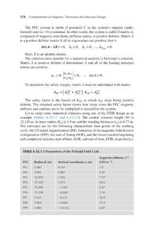
Let us make some numerical estimates using one of the ITER design as an
example (Tables A.12.1.1 and A.12.1.2). The central solenoid height (H) is
12.129 m, its inner radius (R ) is 1.9 m, and the winding thickness (t ) is 0.77 m.
in
w
The estimates are for the following characteristic time points of the working
cycle: the CS initial magnetisation (IM), formation of the magnetic field divertor
configuration (XPF), the start of flattop (SOF), and the fusion reaction beginning
and completion (plasma start of burn, SOB, and end of burn, EOB, respectively).
TABLE A.12.1.1 Parameters of the Poloidal Field Coils
(e)
Supports stiffness c i
−1
PFC Radius R i (m) Vertical coordinate z i (m) (GN m )
PF1 3.883 9.767 1.9
PF2 5.991 9.887 4.47
PF3 12.974 7.305 7.57
PF4 15.360 4.013 46.6
PF5 15.444 −2.265 6.67
PF6 13.194 −9.088 3.16
PF7 9.631 −9.157 26.0
PF8 5.864 −9.808 37.9
PF9 3.883 −10.152 6.07