
Page 401 - Fundamentals of Magnetic Thermonuclear Reactor Design
P. 401
Mechanics of Magnetic Fusion Reactors Chapter | 12 379
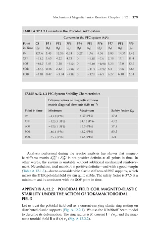
TABLE A.12.1.2 Currents in the Poloidal Field System
Currents in the PFC system (MA)
Point CS PF1 PF2 PF3 PF4 PF5 PF6 PF7 PF8 PF9
in Time (I 0 ) (I 1 ) (I 2 ) (I 3 ) (I 4 ) (I 5 ) (I 6 ) (I 7 ) (I 8 ) (I 9 )
IM 127.6 5.43 13.56 0.24 0.27 1.76 4.36 3.93 14.35 5.42
XPF −33.2 3.65 4.22 4.73 0 −5.82 −7.6 2.18 17.1 11.4
SOF −92.7 1.81 1.58 −6.54 0 −9.03 −8.98 3.23 17.0 12.5
SOB −87.3 0.36 2.42 −7.82 0 −11.9 −7.92 5.4 14.6 6.68
EOB −138 0.47 −3.94 −7.82 0 −12.8 −6.5 6.27 6.18 2.31
TABLE A.12.1.3 PFC System Stability Characteristics
Extreme values of magnetic stiffness
−1
matrix diagonal elements (MN m )
Point in time Minimum Maximum Safety factor, K SF
IM −43.9 (PF8) 1.57 (PF5) 37.8
XPF −125.3 (PF8) 24.12 (PF6) 43.2
SOF −150.1 (PF8) 38.5 (PF6) 37.5
SOB −86.2 (PF8) 43.2 (PF6) 80.5
EOB −25.5 (PF8) 35.5 (PF6) 422
Analysis performed during the reactor analysis has shown that magnet-
m
m
ic stiffness matrix A () + A () is not positive definite at all points in time. In ACS(m)+APF(m)
CS
PF
other words, the system is unstable without additional mechanical reinforce-
ment. Nevertheless, total matrix A is positive definite—and with a good margin
(Table A.12.1.3)—due to a considerable elastic stiffness of PFC supports, which
makes the ITER poloidal field system quite stable. The safety factor is 37.5 at a
minimum and is consistent with the SOF point in time.
APPENDIX A.12.2 POLOIDAL FIELD COIL MAGNETO-ELASTIC
STABILITY UNDER THE ACTION OF TOKAMAK TOROIDAL
FIELD
Let us treat the poloidal field coil as a current-carrying elastic ring resting on
distributed elastic supports (Fig. A.12.2.1). We use the Kirchhoff beam model
to describe its deformation. The ring radius is R; current I = I e , and the mag-
netic toroidal field B = B (r) e (Fig. A.12.2.2).
