
Page 132 - Fundamentals of Ocean Renewable Energy Generating Electricity From The Sea
P. 132
Wave Energy Chapter | 5 123
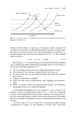
FIG. 5.7 Wave crests that are at an oblique angle to depth contours (dashed lines) refract as they
propagate towards the coast.
familiar law from studies of optics and, in the present context, expresses the
constancy of wavenumber k in the direction parallel to the shore. In other words,
the distance between successive crests measured parallel to the shoreline, L 1 ,
remains constant as the waves travel into shallow water (Fig. 5.7). This condition
may be written as
k sin ψ = k 0 sin ψ 0 = constant (5.47)
Based on Eq. (5.47), refraction diagrams can be generated for given offshore
wave conditions and maps of bathymetry/topography. However, such analysis is
based on the following assumptions [10]:
● The wave energy between wave rays (orthogonals) remains constant.
● The direction of wave advance is perpendicular to the wave crest.
● The speed of the wave of a given period depends only on the water depth at
that location.
● Changes in bathymetry are gradual.
● Waves are long-crested, constant-period, small-amplitude, and monochro-
matic.
● Effects of currents, winds, and reflections from beaches, and underwater
topographic features, are considered negligible.
A typical refraction diagram, for a wave of period T = 10 s, is shown for an
irregular coastline (a headland and two bays) in Fig. 5.8. The wave orthogonals
converge at the headland and diverge in the bays. Because wave energy between
the wave orthogonals remains constant (see the earlier assumptions), this implies
that the wave height will generally increase at the headland and reduce in the
two bays.
As we saw in Eq. (5.46), wave energy flux is a constant, provided no energy
is dissipated, for example, by wave breaking or friction. Now, in the more