
Page 134 - Fundamentals of Ocean Renewable Energy Generating Electricity From The Sea
P. 134
Wave Energy Chapter | 5 125
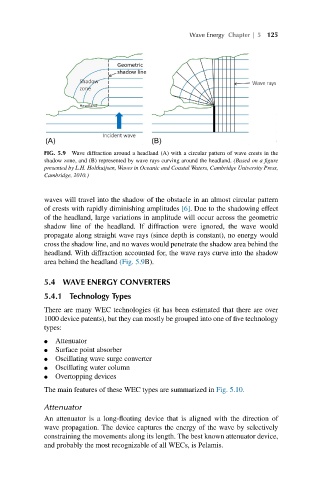
FIG. 5.9 Wave diffraction around a headland (A) with a circular pattern of wave crests in the
shadow zone, and (B) represented by wave rays curving around the headland. (Based on a figure
presented by L.H. Holthuijsen, Waves in Oceanic and Coastal Waters, Cambridge University Press,
Cambridge, 2010.)
waves will travel into the shadow of the obstacle in an almost circular pattern
of crests with rapidly diminishing amplitudes [6]. Due to the shadowing effect
of the headland, large variations in amplitude will occur across the geometric
shadow line of the headland. If diffraction were ignored, the wave would
propagate along straight wave rays (since depth is constant), no energy would
cross the shadow line, and no waves would penetrate the shadow area behind the
headland. With diffraction accounted for, the wave rays curve into the shadow
area behind the headland (Fig. 5.9B).
5.4 WAVE ENERGY CONVERTERS
5.4.1 Technology Types
There are many WEC technologies (it has been estimated that there are over
1000 device patents), but they can mostly be grouped into one of five technology
types:
● Attenuator
● Surface point absorber
● Oscillating wave surge converter
● Oscillating water column
● Overtopping devices
The main features of these WEC types are summarized in Fig. 5.10.
Attenuator
An attenuator is a long-floating device that is aligned with the direction of
wave propagation. The device captures the energy of the wave by selectively
constraining the movements along its length. The best known attenuator device,
and probably the most recognizable of all WECs, is Pelamis.