
Page 205 - Fundamentals of Radar Signal Processing
P. 205
of d, they contribute a term to the complete antenna pattern that does exhibit
spatial aliasing. As a result, the overall antenna pattern can exhibit aliasing in
some circumstances, depending on whether phase or time delay steering is used
for individual elements and across subarrays, the steering direction of the array,
and the bandwidth of the radar waveform. An introduction to these issues is
given in Bailey (2010).
3.3.2 Sampling in Angle
Consider a steerable or scanning antenna, whether mechanically steered
(typically a parabolic dish or slotted flat-plate array, and others) or
electronically steered (phased array), with a 3-dB beamwidth θ radians. Each
3
pulse transmitted samples the reflectivity of the environment in the direction in
which the antenna is pointed. If a region in angular (elevation and azimuth)
space is to be searched, the question arises: how densely in angle must the
space be sampled? That is, how much can the antenna be steered before another
pulse should be transmitted? Smaller angular sampling intervals provide a
better representation of the search volume, but also require more pulses and
therefore more time to search a given volume. Since the antenna voltage pattern
suppresses returns more than about ± θ /2 radians from the antenna boresight,
3
one intuitively expects that to adequately sample the reflectivity of the scene
scanned by the antenna, it will be necessary to make a new measurement every
time it scans by some angle on the order of θ . The Nyquist criterion can be
3
applied to this spatial sampling problem to quantify this expectation.
It was seen in Chap. 2 [Eq. (2.119)] that the observed reflectivity in angle
for a constant range is the convolution of the range-averaged reflectivity with
the two-way antenna voltage pattern. An equivalent expression in just one angle
dimension for simplicity, say azimuth, is
(3.26)
where y(θ; R ) is the complex coherent receiver output as a function of azimuth
0
angle θ at range R , is the range-averaged reflectivity evaluated at range
0
2
R and E (θ) is the two-way voltage pattern in the angular dimension θ. It
0
follows that the Fourier transform in the angle dimension of y is the product of
the Fourier transforms of the antenna pattern and the range-averaged reflectivity.
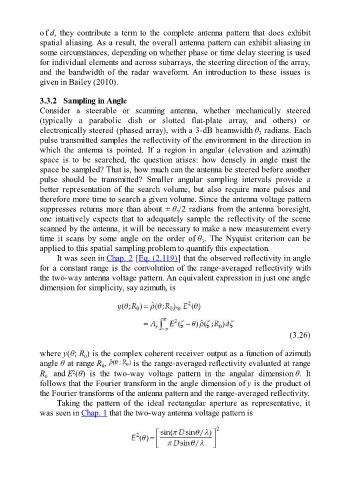
Taking the pattern of the ideal rectangular aperture as representative, it
was seen in Chap. 1 that the two-way antenna voltage pattern is