
Page 362 - Fundamentals of Radar Signal Processing
P. 362
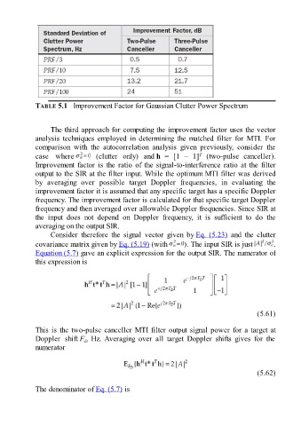
TABLE 5.1   Improvement Factor for Gaussian Clutter Power Spectrum


                     The third approach for computing the improvement factor uses the vector

               analysis  techniques  employed  in  determining  the  matched  filter  for  MTI.  For
               comparison  with  the  autocorrelation  analysis  given  previously,  consider  the
                                                                                T
               case  where             (clutter  only)  and h  =  [1  –  1]   (two-pulse  canceller).
               Improvement  factor  is  the  ratio  of  the  signal-to-interference  ratio  at  the  filter
               output to the SIR at the filter input. While the optimum MTI filter was derived
               by  averaging  over  possible  target  Doppler  frequencies,  in  evaluating  the
               improvement factor it is assumed that any specific target has a specific Doppler

               frequency. The improvement factor is calculated for that specific target Doppler
               frequency and then averaged over allowable Doppler frequencies. Since SIR at
               the  input  does  not  depend  on  Doppler  frequency,  it  is  sufficient  to  do  the
               averaging on the output SIR.
                     Consider  therefore  the  signal  vector  given  by Eq. (5.23)  and  the  clutter

               covariance matrix given by Eq. (5.19) (with                ). The input SIR is just           .
               Equation (5.7) gave an explicit expression for the output SIR. The numerator of
               this expression is


                                                                                                       (5.61)

               This is the two-pulse canceller MTI filter output signal power for a target at
               Doppler  shift F   Hz. Averaging  over  all  target  Doppler  shifts  gives  for  the
                                  D
               numerator


                                                                                                       (5.62)


               The denominator of Eq. (5.7) is