
Page 73 - Fundamentals of Radar Signal Processing
P. 73
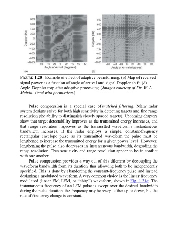
FIGURE 1.20   Example of effect of adaptive beamforming. (a) Map of received
               signal power as a function of angle of arrival and signal Doppler shift. (b)
               Angle-Doppler map after adaptive processing. (Images courtesy of Dr. W. L.
               Melvin. Used with permission.)


                     Pulse  compression  is  a  special  case  of matched  filtering.  Many  radar
               system designs strive for both high sensitivity in detecting targets and fine range

               resolution (the ability to distinguish closely spaced targets). Upcoming chapters
               show that target detectability improves as the transmitted energy increases, and
               that  range  resolution  improves  as  the  transmitted  waveform’s  instantaneous
               bandwidth  increases.  If  the  radar  employs  a  simple,  constant-frequency
               rectangular  envelope  pulse  as  its  transmitted  waveform  the  pulse  must  be
               lengthened to increase the transmitted energy for a given power level. However,
               lengthening the pulse also decreases its instantaneous bandwidth, degrading the

               range resolution. Thus sensitivity and range resolution appear to be in conflict
               with one another.
                     Pulse compression provides a way out of this dilemma by decoupling the
               waveform bandwidth from its duration, thus allowing both to be independently
               specified. This is done by abandoning the constant-frequency pulse and instead

               designing a modulated waveform. A very common choice is the linear frequency
               modulated (linear FM, LFM, or “chirp”) waveform, shown in Fig. 1.21a. The
               instantaneous frequency of an LFM pulse is swept over the desired bandwidth
               during the pulse duration; the frequency may be swept either up or down, but the
               rate of frequency change is constant.