
Page 156 - Fundamentals of The Finite Element Method for Heat and Fluid Flow
P. 156
148
Exercise 5.8.5 In Exercise 5.8.1, if the thickness increases uniformly from 1 cm from the
bottom edge to 3 cm at the top edge, re-solve the problem with (a) two triangles and (b) eight
triangles. STEADY STATE HEAT CONDUCTION IN MULTI-DIMENSIONS
Exercise 5.8.6 Calculate the stiffness matrix and loading vector for the axisymmetric ele-
3
ment shown in Figure 5.19 with a heat generation of G = 1W/cm , the heat transfer coef-
2
◦
ficient on the side ij is 1.0 W/cm K and the ambient temperature is 25 C. The heat flux on
2
◦
the side jk is equal to 0.5 W/cm . Assume the thermal conductivities k r = k z = 1.5W/m C.
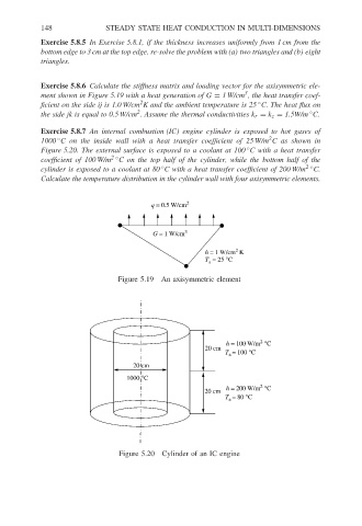
Exercise 5.8.7 An internal combustion (IC) engine cylinder is exposed to hot gases of
2
1000 C on the inside wall with a heat transfer coefficient of 25 W/m C as shown in
◦
◦
Figure 5.20. The external surface is exposed to a coolant at 100 C with a heat transfer
coefficient of 100 W/m 2 ◦ C on the top half of the cylinder, while the bottom half of the
◦
cylinder is exposed to a coolant at 80 C with a heat transfer coefficient of 200 W/m 2 ◦ C.
Calculate the temperature distribution in the cylinder wall with four axisymmetric elements.
q = 0.5 W/cm 2
G = 1 W/cm 3
2
h = 1 W/cm K
T = 25 °C
a
Figure 5.19 An axisymmetric element
2
h = 100 W/m °C
20 cm
T = 100 °C
a
20 cm
1000 °C
2
h = 200 W/m °C
20 cm
T = 80 °C
a
Figure 5.20 Cylinder of an IC engine