
Page 241 - Fundamentals of The Finite Element Method for Heat and Fluid Flow
P. 241
CONVECTION HEAT TRANSFER
where C µ is a constant equal to 0.09 and l m is the Prandtl mixing length, which is assumed
to be l m = 0.4y,where y is the shortest distance from a node to the solid wall. The turbulent
kinetic energy may be obtained by solving the following transport equation: 233
∂κ ∂u i κ ∂ ν t ∂κ R ∂u i
+ = ν + + τ ij − ε (7.204)
∂t ∂x j ∂x i Prt ∂x i ∂x j
where Prt is the turbulent Prandtl number that is normally taken to be equal to unity. For
the one equation model, the isotropic turbulence energy dissipation rate ε is
κ 3/2
ε = C D (7.205)
L
3 1/4
where the length scale of the turbulence L = l m (C D /C µ ) and C D is equal to 1.
7.12.1 Solution procedure and result
The solution procedure follows the steps of the CBS scheme as discussed previously in
Section 7.6. If isothermal flow is of interest, then the temperature equation is ignored, and a
solution to the turbulent kinetic energy equation becomes the fourth step. For non-isothermal
problems, the temperature equation is solved at Step 4, and the turbulent kinetic energy
equation is solved at Step 5. At each and every time step, the turbulent eddy viscosity is
calculated and substituted into the averaged momentum equations. The example solved is
for the case of isothermal flow through a two-dimensional, horizontal rectangular channel.
The problem definition is the same as for the example given in Section 7.10. The difference
being that the extra boundary condition for the turbulent kinetic energy needs to be imposed.
The turbulent kinetic energy value is fixed at the inlet (κ = 0.1) and zero on the walls. The
1
0.8
CBS
Vertical Distance 0.4
Exp. data
0.6
0.2
0
0 0.2 0.4 0.6 0.8 1
Horizontal velocity
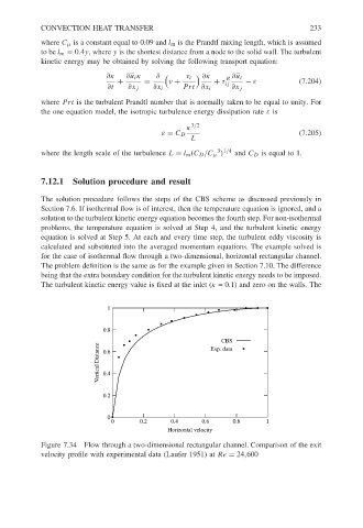
Figure 7.34 Flow through a two-dimensional rectangular channel. Comparison of the exit
velocity profile with experimental data (Laufer 1951) at Re = 24,600