
Page 238 - Fundamentals of The Finite Element Method for Heat and Fluid Flow
P. 238
230
2.5
Aung and Worku CONVECTION HEAT TRANSFER
2
CBS
1.5
Vertical velocity 0.5 1
0
−0.5
0 0.2 0.4 0.6 0.8 1
Horizontal distance
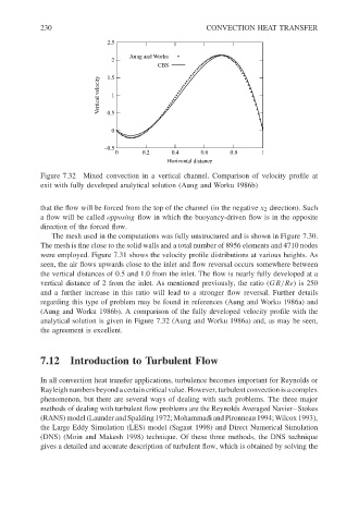
Figure 7.32 Mixed convection in a vertical channel. Comparison of velocity profile at
exit with fully developed analytical solution (Aung and Worku 1986b)
that the flow will be forced from the top of the channel (in the negative x 2 direction). Such
a flow will be called opposing flow in which the buoyancy-driven flow is in the opposite
direction of the forced flow.
The mesh used in the computations was fully unstructured and is shown in Figure 7.30.
The mesh is fine close to the solid walls and a total number of 8956 elements and 4710 nodes
were employed. Figure 7.31 shows the velocity profile distributions at various heights. As
seen, the air flows upwards close to the inlet and flow reversal occurs somewhere between
the vertical distances of 0.5 and 1.0 from the inlet. The flow is nearly fully developed at a
vertical distance of 2 from the inlet. As mentioned previously, the ratio (GR/Re) is 250
and a further increase in this ratio will lead to a stronger flow reversal. Further details
regarding this type of problem may be found in references (Aung and Worku 1986a) and
(Aung and Worku 1986b). A comparison of the fully developed velocity profile with the
analytical solution is given in Figure 7.32 (Aung and Worku 1986a) and, as may be seen,
the agreement is excellent.
7.12 Introduction to Turbulent Flow
In all convection heat transfer applications, turbulence becomes important for Reynolds or
Rayleigh numbers beyond a certain critical value. However, turbulent convection is a complex
phenomenon, but there are several ways of dealing with such problems. The three major
methods of dealing with turbulent flow problems are the Reynolds Averaged Navier–Stokes
(RANS) model (Launder and Spalding 1972; Mohammadi and Pironneau 1994; Wilcox 1993),
the Large Eddy Simulation (LES) model (Sagaut 1998) and Direct Numerical Simulation
(DNS) (Moin and Makesh 1998) technique. Of these three methods, the DNS technique
gives a detailed and accurate description of turbulent flow, which is obtained by solving the