
Page 233 - Fundamentals of The Finite Element Method for Heat and Fluid Flow
P. 233
225
CONVECTION HEAT TRANSFER
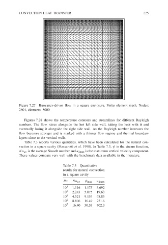
Figure 7.27 Buoyancy-driven flow in a square enclosure. Finite element mesh. Nodes:
2601, elements: 5000
Figures 7.28 shows the temperature contours and streamlines for different Rayleigh
numbers. The flow raises alongside the hot left side wall, taking the heat with it and
eventually losing it alongside the right side wall. As the Rayleigh number increases the
flow becomes stronger and is marked with a thinner flow regime and thermal boundary
layers close to the vertical walls.
Table 7.3 reports various quantities, which have been calculated for the natural con-
vection in a square cavity (Massarotti et al. 1998). In Table 7.3, ψ is the stream function,
Nu av is the average Nusselt number and u 2max is the maximum vertical velocity component.
These values compare very well with the benchmark data available in the literature.
Table 7.3 Quantitative
results for natural convection
in a square cavity
Ra Nu av ψ max u 2max
10 3 1.116 1.175 3.692
10 4 2.243 5.075 19.63
10 5 4.521 9.153 68.85
10 6 8.806 16.49 221.6
10 7 16.40 30.33 702.3