
Page 43 - Fundamentals of The Finite Element Method for Heat and Fluid Flow
P. 43
SOME BASIC DISCRETE SYSTEMS
Q 1 2 2 35
1
5
3
3 4 4
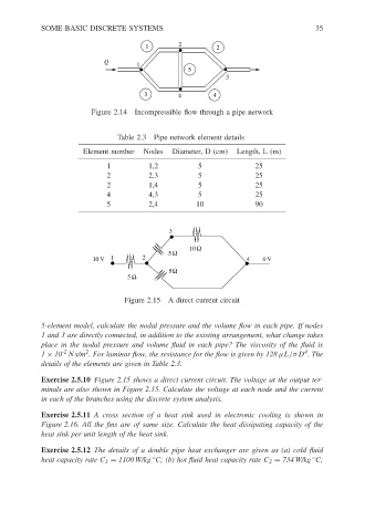
Figure 2.14 Incompressible flow through a pipe network
Table 2.3 Pipe network element details
Element number Nodes Diameter, D (cm) Length, L (m)
1 1,2 5 25
2 2,3 5 25
2 1,4 5 25
4 4,3 5 25
5 2,4 10 90
3
10 Ω
5 Ω
10 V 1 2 4 0 V
5Ω
5 Ω
Figure 2.15 A direct current circuit
5-element model, calculate the nodal pressure and the volume flow in each pipe. If nodes
1 and 3 are directly connected, in addition to the existing arrangement, what change takes
place in the nodal pressure and volume fluid in each pipe? The viscosity of the fluid is
4
2
-2
1 × 10 Ns/m . For laminar flow, the resistance for the flow is given by 128 µL/πD .The
details of the elements are given in Table 2.3.
Exercise 2.5.10 Figure 2.15 shows a direct current circuit. The voltage at the output ter-
minals are also shown in Figure 2.15. Calculate the voltage at each node and the current
in each of the branches using the discrete system analysis.
Exercise 2.5.11 A cross section of a heat sink used in electronic cooling is shown in
Figure 2.16. All the fins are of same size. Calculate the heat dissipating capacity of the
heat sink per unit length of the heat sink.
Exercise 2.5.12 The details of a double pipe heat exchanger are given as (a) cold fluid
◦
heat capacity rate C 1 = 1100 W/kg C; (b) hot fluid heat capacity rate C 2 = 734 W/kg C;
◦