Page 40 - Fundamentals of The Finite Element Method for Heat and Fluid Flow
P. 40

32
                                                          A 2    SOME BASIC DISCRETE SYSTEMS
                                                                k 2
                                             A 1      k 1

                                         q                                   h, T a
                                                         A 3    k 3


                                                      L 1       L 2


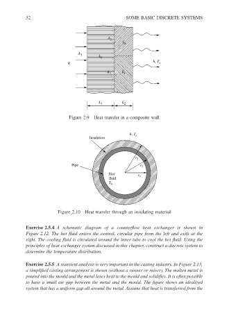
                                          Figure 2.9 Heat transfer in a composite wall


                                                                   h, T a
                                                  Insulation


                                                                     r 2
                                           Pipe                        r 3

                                                          Hot         r
                                                          fluid        1
                                                          T h


                                     Figure 2.10 Heat transfer through an insulating material


                        Exercise 2.5.4 A schematic diagram of a counterflow heat exchanger is shown in
                        Figure 2.12. The hot fluid enters the central, circular pipe from the left and exits at the
                        right. The cooling fluid is circulated around the inner tube to cool the hot fluid. Using the
                        principles of heat exchanger system discussed in this chapter, construct a discrete system to
                        determine the temperature distribution.

                        Exercise 2.5.5 A transient analysis is very important in the casting industry. In Figure 2.13,
                        a simplified casting arrangement is shown (without a runner or raiser). The molten metal is
                        poured into the mould and the metal loses heat to the mould and solidifies. It is often possible
                        to have a small air gap between the metal and the mould. The figure shows an idealized
                        system that has a uniform gap all around the metal. Assume that heat is transferred from the
   35   36   37   38   39   40   41   42   43   44   45