Page 36 - Fundamentals of The Finite Element Method for Heat and Fluid Flow
P. 36

28
                                                                      W 2 , T 18
                                                10 W 2 , T 10  14  14  SOME BASIC DISCRETE SYSTEMS
                                                                      18
                                           W 1
                                                 8       7      6       5
                                             9      8       7      6       5
                                           T 9
                                                11     13      15     17
                                          W 1
                                                 1       2      3       4
                                          T 1  1    2       3      4       5
                                                12     12      16     16
                                                            (a)
                                                          W 2 , T 11  − Node
                                                                     − Element
                                                           11

                                               W 1 , T 1
                                                          1
                                                   1             2
                                                           12
                                                            (b)

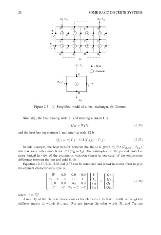
                                 Figure 2.7 (a) Simplified model of a heat exchanger, (b) Element


                           Similarly, the heat leaving node 11 and entering element 1 is

                                                       Q 11 = W 2 T 11                      (2.36)
                        and the heat leaving element 1 and entering node 12 is

                                              Q 12 = W 2 T 11 − UA(T 11,12 − T 1,2 )        (2.37)
                           In this example, the heat transfer between the fluids is given by UA(T 11,12 − T 1,2 ),
                        whereas some other models use UA(T 12 − T 2 ). The assumption in the present model is
                        more logical in view of the continuous variation (linear in our case) of the temperature
                        difference between the hot and cold fluids.
                           Equations 2.33, 2.34, 2.36 and 2.37 can be combined and recast in matrix form to give
                        the element characteristics, that is,
                                                                          
                                           W 1   0.0   0.0   0.0
                                                                   T 1    Q 1 
                                                                            
                                         W 1 − C −C     C     C             
                                                                  T 2     Q 2
                                                                      =                   (2.38)
                                           0.0   0.0         0.0
                                                      W 2        T 11  Q 11
                                                                            
                                            C     C  W 2 − C −C    T 12    Q 12  
                                  UA
                        where C =   .
                                  2
                           Assembly of the element characteristics for elements 1 to 8 will result in the global
                        stiffness matrix in which Q 1 ,and Q 10 are known (in other words T 1 ,and T 10 are
   31   32   33   34   35   36   37   38   39   40   41