
Page 33 - Fundamentals of The Finite Element Method for Heat and Fluid Flow
P. 33
SOME BASIC DISCRETE SYSTEMS
where ‘f ’ is the Moody friction factor, which is a function of the Reynolds number and
the pipe roughness. The fluidity matrix will contain known functions of the flow rate ‘Q’
instead of constants. Hence, the problem becomes nonlinear. 25
2.2.3 Heat transfer in heat sinks (combined conduction–convection)
In order to increase the heat dissipation by convection from a given primary surface,
additional surfaces may be added. The additional material added is referred to either as an
‘Extended Surface’ or a ‘Fin’. A familiar example is in motorcycles, in which fins extend
from the outer surface of the engine to dissipate more heat by convection. A schematic
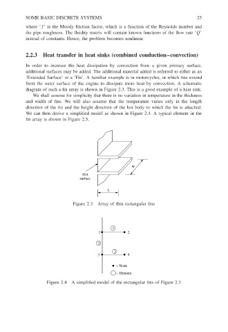
diagram of such a fin array is shown in Figure 2.3. This is a good example of a heat sink.
We shall assume for simplicity that there is no variation in temperature in the thickness
and width of fins. We will also assume that the temperature varies only in the length
direction of the fin and the height direction of the hot body to which the fin is attached.
We can then derive a simplified model as shown in Figure 2.4. A typical element in the
fin array is shown in Figure 2.5.
W
Hot
surface
L
Figure 2.3 Array of thin rectangular fins
1
1 2
2
3
3 4
− Node
− Element
Figure 2.4 A simplified model of the rectangular fins of Figure 2.3