
Page 35 - Fundamentals of The Finite Element Method for Heat and Fluid Flow
P. 35
SOME BASIC DISCRETE SYSTEMS
Equation 2.31 reduces to Equation 2.14 in the absence of convection from the surface.
Also, if the terms (T i + T j )/2 in Equation 2.31 are replaced by (2T i + T j )/3, then we
obtain the standard Galerkin weighted residual form discussed in Example 3.5.1. 27
2.2.4 Analysis of a heat exchanger
The performance of a heat exchanger can be calculated in terms of its effectiveness for
a given condition (Holman 1989; Incropera and Dewitt 1990). In order to determine the
effectiveness of a heat exchanger, we have to calculate the outlet temperatures of both
the hot fluid and the cold fluid for the given inlet temperatures. The overall heat transfer
coefficient may be a constant or could vary along the heat exchanger.
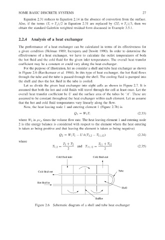
For the purpose of illustration, let us consider a shell and tube heat exchanger as shown
in Figure 2.6 (Ravikumaur et al. 1984). In this type of heat exchanger, the hot fluid flows
through the tube and the tube is passed through the shell. The cooling fluid is pumped into
the shell and thus the hot fluid in the tube is cooled.
Let us divide the given heat exchanger into eight cells as shown in Figure 2.7. It is
assumed that both the hot and cold fluids will travel through the cell at least once. Let the
overall heat transfer coefficient be U and the surface area of the tubes be ‘A’. These are
assumed to be constant throughout the heat exchanger within each element. Let us assume
that the hot and cold fluid temperatures vary linearly along the flow.
Now, the heat leaving node 1 and entering element 1 (Figure 2.7b) is
Q 1 = W 1 T 1 (2.33)
where W 1 is ρc p times the volume flow rate. The heat leaving element 1 and entering node
2 is (the energy balance is considered with respect to the element where the heat entering
is taken as being positive and that leaving the element is taken as being negative)
Q 2 = W 1 T 1 − UA(T 1,2 − T 11,12 ) (2.34)
where
T 1 + T 2 T 11 + T 12
T 1,2 = and T 11,12 = (2.35)
2 2
Cold fluid inlet Cold fluid exit
Cold fluid out Tube
Hot fluid in
Shell
Baffles
Figure 2.6 Schematic diagram of a shell and tube heat exchanger